Rockwell Automation 1794-APB/B FLEX I/O PROFIBUS Adapter Module User Manual User Manual
Page 38
2–18
How Communication Takes Place and I/O Image Table Mapping
Publication 1794ĆUM057B-EN-P - November 2001
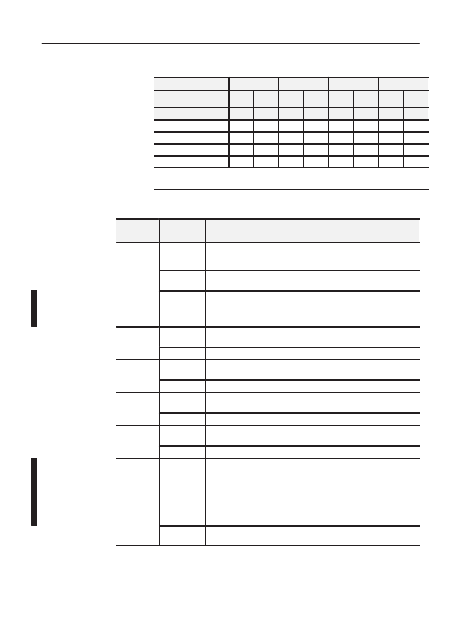
1794ĆOE4/B Range Selection Bits (Write Word 6)
Channel No.
Channel 0
Channel 1
Channel 2
Channel 3
F0
C0
F1
C1
F2
C2
F3
C3
Decimal Bit
00
08
01
09
02
10
03
11
4-20mA
0
1
0
1
0
1
0
1
0-10V dc/0-20mA
1
0
1
0
1
0
1
0
Ć10 to +10V dc
1
1
1
1
1
1
1
1
Off
1
0
0
0
0
0
0
0
0
C = Configure select bit
F = Full range bit
1
When configured to off, individual channels will return 0V.
1794ĆOE4 Word/Bit Descriptions
Word
Decimal Bit
(Octal Bit)
Definition
Bits 00Ć03
Current outputs only - When set (1), the wire on the output is broken or the load
resistance is too high. Bit 00 corresponds to channel 0, bit 01 corresponds to
channel 2, and so on.
Read Word 1
Bits 04Ć14
(04-16)
Not used - set to 0
Bit 15 (17)
Power Up bit - included in series B modules only. This bit is always 0 in
series A modules. This bit is set to 1 when all bits in the configuration
register (write word 5) are 0 (unconfigured state). The configuration register
can be cleared by either a reset, or by the user writing all zeroes to it.
Write Word 1
Bits 00-14
(00-16)
Channel 0 analog data - 12Ćbit left justified two's complement number; unused
lower bits are zero; 4Ć20mA uses all 16 bits.
Bits 15 (17)
Channel 0 analog data sign bit.
Word 2
Bits 00-14
(00-16)
Channel 1 analog data - 12Ćbit left justified two's complement number; unused
lower bits are zero; 4Ć20mA uses all 16 bits.
Bits 15 (17)
Channel 1 analog data sign bit.
Word 3
Bits 00-14
(00-16)
Channel 2 analog data - 12Ćbit left justified two's complement number; unused
lower bits are zero; 4Ć20mA uses all 16 bits.
Bits 15 (17)
Channel 2 analog data sign bit.
Word 4
Bits 00-14
(00-16)
Channel 3 analog data - 12Ćbit left justified two's complement number; unused
lower bits are zero; 4Ć20mA uses all 16 bits.
Bits 15 (17)
Channel 3 analog data sign bit.
Word 5
Bits 00-03
Multiplex control bits (M) for individual channels. These bits control the safe
state analog outputs. - Bit 00 corresponds to output channel 0, bit 01
corresponds to output channel 1, and so on.
1 = use words 0, 1, 2 or 3 as directed by channel number n
0 = use words 10, 11, 12 or 13 as directed by channel number n
When bits 00Ć03 are all cleared (0) simultaneously by a communication error or
user choice thru the programmable controller program, word 5 full range and
configure select bits are preserved at their last setting.
Bits 04Ć15
(04Ć17)
Not used - set to 0.