Rockwell Automation 1794-APB/B FLEX I/O PROFIBUS Adapter Module User Manual User Manual
Page 30
2–10
How Communication Takes Place and I/O Image Table Mapping
Publication 1794ĆUM057B-EN-P - November 2001
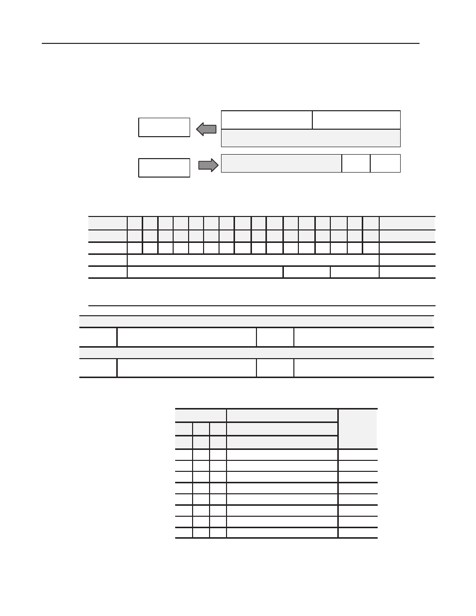
1794ĆIB8S - 8Ćpoint Discrete Sensor Input Module Image Table
Mapping
Module Image
Inputs
Delay
Time
Status
I/O Image
Not used
Not used
Input Size
Output Size
0 or 1 Word
1 or 2 Words
Delay
Time
Read
Write
1794ĆIB8S Memory Map
Decimal Bit 15 14 13 12
11 10 09
08
07
06
05
04
03
02
01
00
Size
Octal Bit
17 16 15 14 13 12
11
10
07
06
05
04
03
02
01
00
Read Words
S7 S6 S5 S4 S3 S2 S1 S0 D7 D6 D5 D4 D3 D2 D1 D0
Read Word 1
Not used
Read Word 2
Not used
DT 12-15
DT 00-11
Write Word 1
Where S = Status of input (where S1 corresponds to the diagnostic bit for input 1, S2 corresponds to the diagnostic bit for input 2, etc.)
D = Input Data (where D0 corresponds to input 0, D1 corresponds to input 1, etc.
DT = Input Delay Time (where DT 00-11 corresponds to inputs 0 thru 11; DT 12-15 corresponds to inputs 12 thru 15.
Make certain that the delay time for 00-11 is the same as the delay time for 12-15.
Smart Sensor
Bits
08-15
S = Diagnostic data - 1 = Fault present (Smart)
0 = Normal (no errors)
Bits
00-07
D = Input data
1 = Sensor on
0 = Sensor off
Standard Sensor
Bits
08-15
S = Diagnostic data - 1 = Diagnostics not disabled
0 = Normal (Disabled)
Bits
00-07
D = Input data
1 = Sensor on
0 = Sensor off
1794ĆIB8S Input Delay Times
Bits
Description
S
02
01
00 Delay Time for Inputs 00-11
Selected
Delay Time
05
04
03 Delay Time for Inputs 12-15
y
0
0
0
Delay Time 0 (default)
512
µ
s
0
0
1
Delay Time 1
1ms
0
1
0
Delay Time 2
2ms
0
1
1
Delay Time 3
4ms
1
0
0
Delay Time 4
8ms
1
0
1
Delay Time 5
16ms
1
1
0
Delay Time 6
32ms
1
1
1
Delay Time 7
64ms