Rockwell Automation 1794-APB/B FLEX I/O PROFIBUS Adapter Module User Manual User Manual
Page 101
4–9
Configure the Adapter for Master/Slave Communication
Publication 1794ĆUM057B-EN-P - November 2001
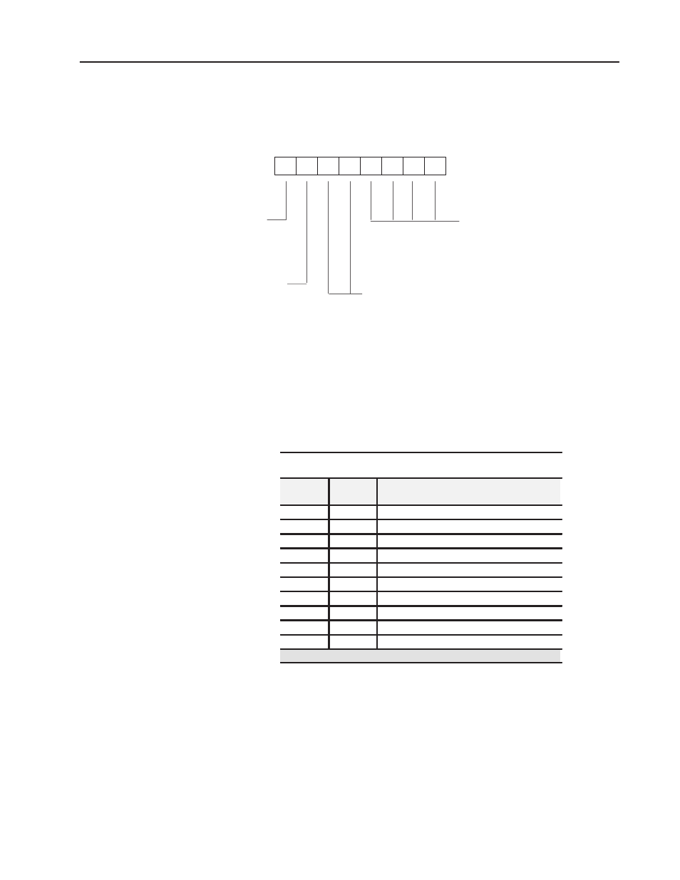
The identifier byte and its format are described in the following
illustration. This byte is defined in Part 3 of the PROFIBUS
standard.
7
6
5
4
3
2
1
0
Most Significant Bit
Least Significant Bit
Bit Number
Length of data
00
1 byte resp.
1 word
•
•
•
15
16 byte resp. 16 words
input/output
00
specific identifier formats
01
input
10
output
11
input-output
length
format
1
0 byte
byte structure
1 word
word structure
concistency over
0
byte or word
1
whole length
The maximum size of this identifier area is 17 bytes. If no FLEX I/O
modules are installed in the upper slots, the length may be less.
Consistency must be over a word.
Check Configuration Example
Check Configuration Message when used with Send Parameter Auto
Configure or Condensed Format (Length 10 bytes)
Name
Identifier
Byte
Description
Octet 1:
50h
Input Status Word (input - 1 word)
Octet 2:
60h
Output Status Word (output - 1 word)
Octet 3:
51h
Slot 1, input module 2 words
Octet 4:
60h
Slot 1, output module 1 word
Octet 5:
00h
Slot 2, input module empty
Octet 6:
60h
Slot 2, output module 1 word
Octet 7:
57h
Slot 3, input module 8 words
Octet 8:
60h
Slot 3, output module 1 word
Octet 9:
50h
Slot 4, input module empty
Octet 10:
65h
Slot 4, output module 6 words
I/O sizes configured: 22 input bytes, 20 output bytes
Refer to your configuration tool publications for information on how
and where to enter this data.