Rockwell Automation 1794-APB/B FLEX I/O PROFIBUS Adapter Module User Manual User Manual
Page 40
2–20
How Communication Takes Place and I/O Image Table Mapping
Publication 1794ĆUM057B-EN-P - November 2001
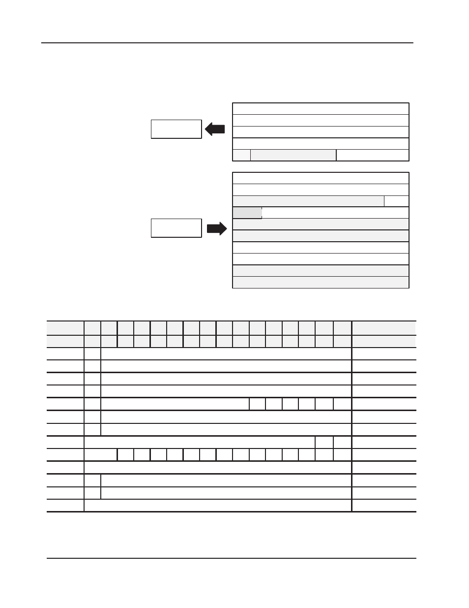
1794ĆIE4XOE2 Series B - Analog Combo Module Image Table
Mapping
Module Image
I/O Image
Input Data Channel 0
Input Data Channel 1
Input Data Channel 2
Input Data Channel 3
Output Data Channel 0
Output Data Channel 1
Underrange & Diag.
Not used
Not used
Not used
Not used
Not used
Full Range and Configure Select
Not used
Input Size
Output Size
0 to 8 Words
0 to 5 Words
Read
Write
M0
PU
Output Channel 0 Safe State
Output Channel 1 Safe State
M1
1794ĆIE4XOE2 Memory Map
Dec. Bit
15
14
13
12
11
10
09
08
07
06
05
04
03
02
01
00
Size
Oct. Bit
17
16
15
14
13
12
11
10
07
06
05
04
03
02
01
00
Read/Write Words
S
Analog Value Input Channel 0
Read Word 1
S
Analog Value Input Channel 1
Read Word 2
S
Analog Value Input Channel 2
Read Word 3
S
Analog Value Input Channel 3
Read Word 4
PU
Not used - set to 0
W1 W0 U3
U2
U1
U0
Read Word 5
S
Analog Data - Output Channel 0
Write Word 1
S
Analog Data - Output Channel 1
Write Word 2
Not used - set to 0
M1
M0
Write Word 3
Not used
C5
C4
C3
C2
C1
C0
0
0
F5
F4
F3
F2
F1
F0
Write Word 4
Not used - set to 0
Write Word 5 and 6
S
Safe State Value - Output Channel 0
Write Word 7
S
Safe State Value - Output Channel 1
Write Word 8
Not used - set to 0
Write Word 9 and 10
Where:
S = sign bit (in 2's complement)
W = Diagnostic bits for current output wire broken or load resistance high. (Not used on voltage outputs.)
U= Underrange bits for 4Ć20mA inputs
PU= Power up bitPU= Power up bit - included in series B modules only.
M = Multiplex control bits
C = Configure select bit
F = Full range bit