Monitor screen – Rockwell Automation 1771-CFM,D17716.5.99 CONFIGURABLE FLOWMET User Manual
Page 91
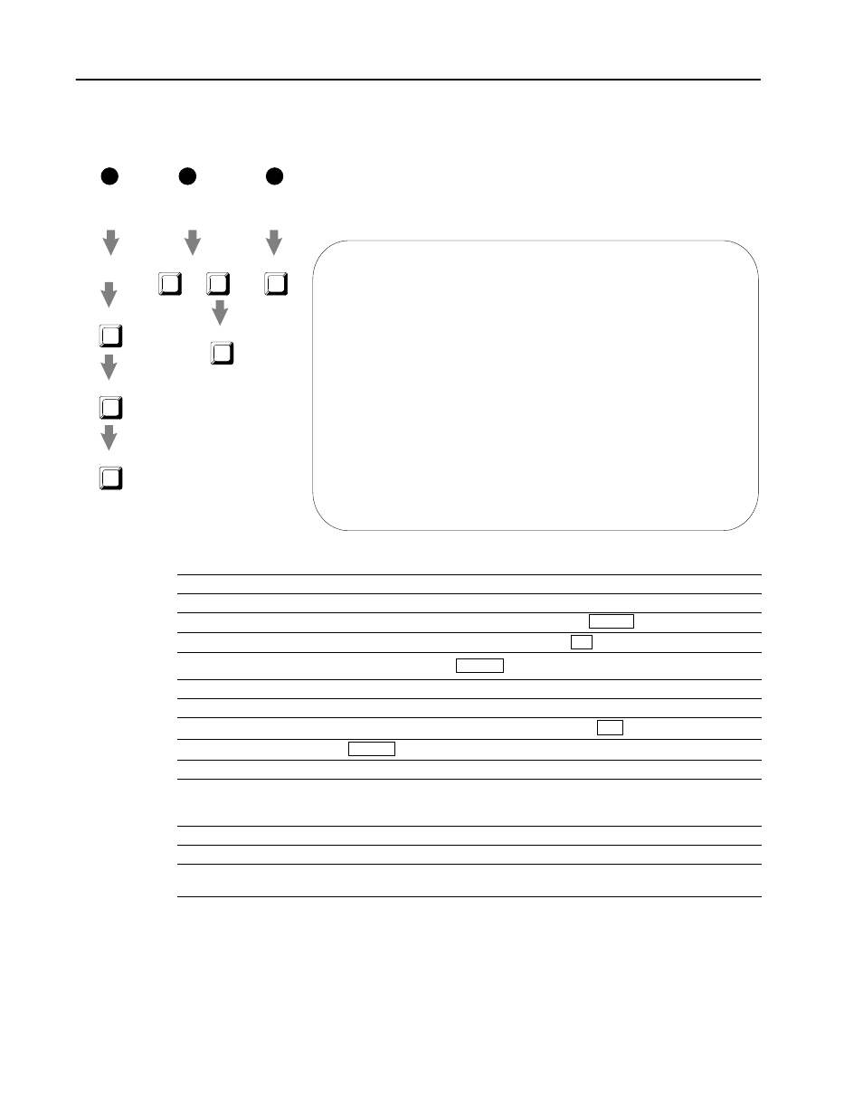
Counter Setup
or Output Setup
or BT Data
Cursor to
BT instruction
I/O Module
System Overview
F3
F1
F8
Data Monitor
I/O Monitor
Monitor
or
a
b
F5
Monitor
or
c
Choose one:
Ladder Editor
Main Menu
F4
Output Setup
F2
Edit
F4
Output Setup
or
Using I/O Configuration Software
E–6
Publication 1771Ć6.5.99 - December 1995
Monitor Screen
Use the monitor screen to check and verify the configuration data.
The values on this screen reflect the data received the last time a
BTR was completed. The processor must be in Run mode if you
want to receive current data from the module.
1771–CFM Series A Monitor Rack–Group–Module: 0–0–0
ch –––––– frequency ––––––– total acceleration prover total/ alarms (*)
% full scale stored count
0 43.0 .07 ( 23) 0 –––
1 –––
2 15,498 12.91 ( 4231) 4,349,126 0 0 –––
3 258 12.92 ( 4233) 2,047,108 0 0 OF
(*) AC=acceleration SP=overspeed OF=overflow OR=overrange
ch mode direction prover | output current tied to
status | number status channel
0 high–resolution frequency | 0 off 0
1 (not used) | 1 off 2
2 totalizer done | 2 on 0
3 nonresettable totalizer done | 3 off 0
Has module received valid BTW since powerup? yes BTW error code: none
Press a function key.
Rem RUN mod 1 of 1 Addr#42:CFM4B
Change I/O Channel Output BT Data
Mode Ovrview Setup Setup Tables
F1 F2 F3 F4 F6
This field
Displays
ch
the input channel (0 to 3).
frequency
the frequency in Hz and % full scale
total
scaled total counts, using scaling from the Channel Setup screen
T, NRT
acceleration
the acceleration as a change per second in scaled frequency
all
prover total/
stored count
the stored count or Prover run result
T, NRT
alarms
the alarm activated (SP=overspeed, AC=acceleration, OF=overflow, OR=overrange)
mode
input channel's current mode of operation
direction
the direction of rotation CW (clockwise) or CCW (counterclockwise) DS
prover status
prover status
T, NRT
output number
the output channel (0 to 3)
current status
the state of the current output (ON or OFF) Ċ these values reflect the data received the last time a
BTR was completed (the PLC processor must be in Run mode if you want to receive current
data from the CFM module)
tied to channel
which input channel the output is tied to
module power-up
whether a BTW has successfully occurred since powerĆup (YES or NO)
BTW error code
an error code is (If an error occurred in the last BTW) Ċ error codes 1 to 60 are word numbers where
invalid configuration was programmed in the BTW data file