Plcć3 family processor – Rockwell Automation 1771-CFM,D17716.5.99 CONFIGURABLE FLOWMET User Manual
Page 31
3–3
Edit Your Ladder Logic Program
Publication 1771Ć6.5.99 - December 1995
PLCĆ3 Family Processor
Block transfer instructions with the PLC-3 processor use a control
file and a data file. The block transfer control file contains the data
table section for module location, the address of the block transfer
data file and other related data. The block transfer data file stores
data that you want transferred to the module (when programming a
BTW) or from the module (when programming a BTR).
The programming terminal prompts you to create a control file when
a block transfer instruction is being programmed. The same block
transfer control file is used for both the read and write
instructions for your module. A different block transfer control
file is required for every module.
13
U
CFM BTR
Error Bit
B17:0
EN
BTR
BLOCK TRANSFER READ
Rack
Group
Slot
Data File
3
2
1
N18:101
Length
Control
0
B17:0
EN
BTW
BLOCK TRANSFER WRITE
Rack
Group
Slot
Data
3
2
1
N18:1
DN
Length
Control
0
B17:0
5
B17:0
B17:0
15
ER
DN
ER
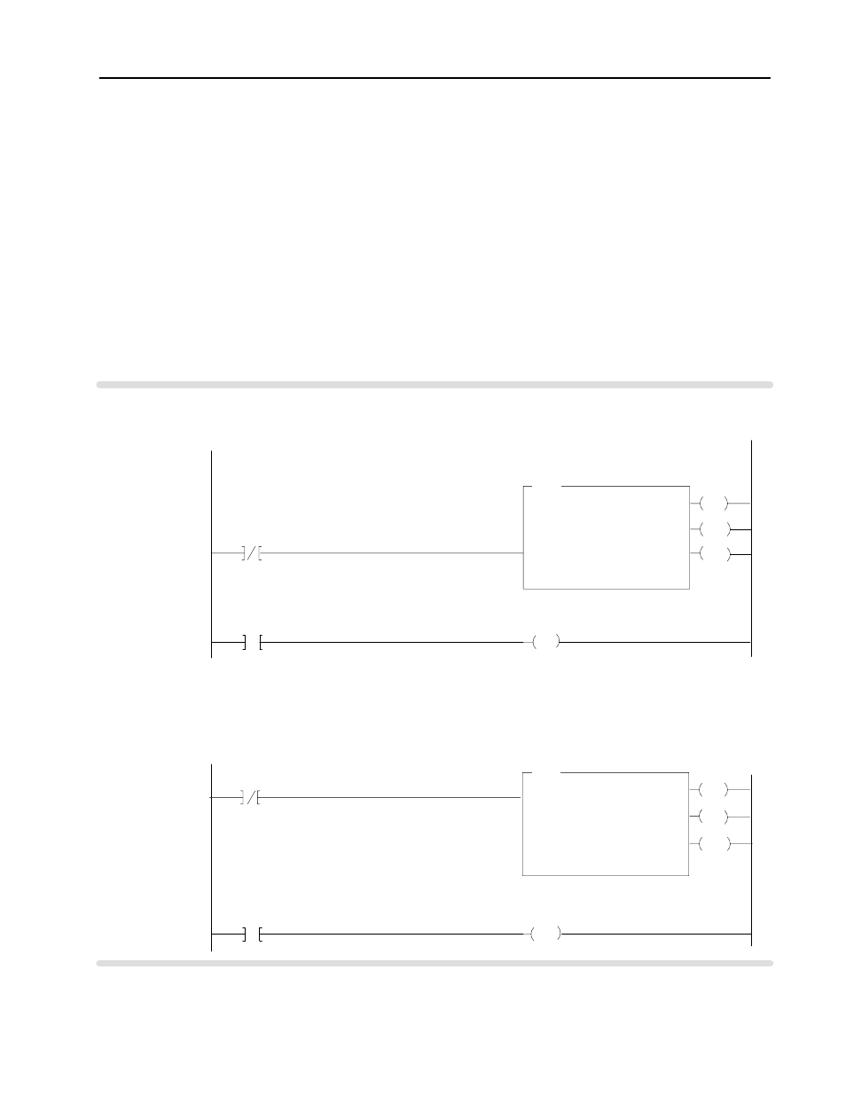
Rung M:0
The CFM module is located in rack 3, I/O group 2, slot 1. The control file is a 10 word file starting at B17:0 that is shared
by the BTR/BTW. The data obtained by the PLC3 processor is placed in memory starting at location N18:101, and with
the default length of 0, is 41 words long.
CFM BTR
Done Bit
CFM BTR/BTW
Control Block
The CFM module is located in rack 3, I/O group 2, slot 1. The control file is a 10 word file starting at B17:0 that is shared
by the BTR/BTW. The data sent by the PLCĆ3 processor to the CFM module is from PLC memory starting at N18:1, and
with the default length of 0, is 60 words long.
13
CFM BTR
Error Bit
B17:0
CFM BTW
Done Bit
CFM BTR/BTW
Control Block
3
B17:0
3
B17:0
U
CFM BTW
Error Bit
CFM BTW
Error Bit
PLCĆ3 Processor
Program Example