C-10, Interpret status indicators, Additional feature – Rockwell Automation 1771-CFM,D17716.5.99 CONFIGURABLE FLOWMET User Manual
Page 74: Ttl inputs (5-40v dc)
Replace Your QRC Module
C–10
Publication 1771Ć6.5.99 - December 1995
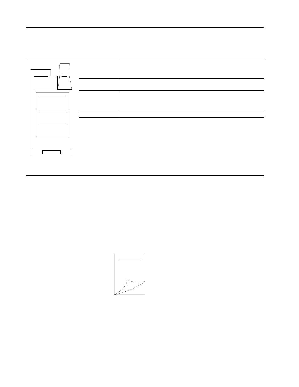
Interpret Status Indicators
Indicators
If indicator
➀
Is ON
Is OFF
ACTIVE
the CFM module is receiving power and
operational
a. Check FAULT LED Ċ if on, follow the
steps listed under if FAULT is ON.
b. Check power supply LEDs.
INPUTS
(F0 & F2)
F0 - flashes with pulses at Channel A
F2 - flashes with pulses at Channel B
a signal is not present at the designated
input terminal (low)
ACTIVE
INPUTS/OUTPUTS
F0 F1 F2 F3
G0 G1 G2 G3
O0 O1 O2 O3
OUTPUTS
➁
(O0 & O1)
O0 - indicates Channel A frequency
is
≥
15,800Hz
O1 - indicates Channel B frequency
is
≥
15,800Hz
the output is off
S S S S
STATUS
O0 O1 O2 O3
STATUS
S3
BTR is occurring
BTR is not occurring
S0 S1 S2 S3
S4 S5 S6 S7
FAULT
STATUS
FAULT
1. Turn off power to the I/O chassis
backplane and wiring arm.
2. Reseat the CFM (QRC) module in
the I/O chassis.
3. Restore power to the I/O chassis
backplane and wiring arm.
Important: If the fault LED remains on,
there may be an internal problem.
Contact your local AllenĆBradley
representative for additional assistance.
normal operation
➀
All other LED's are OFF in normal operation.
➁
Outputs are not active if PLC processor is faulted or in Program mode.
Additional Feature
When you replace your existing QRC module with the CFM module,
you can set input channel jumpers for:
•
TTL inputs (5-40v dc)
•
500mV ac sensitivity for improved noise immunity
For additional information on setting the input channel jumpers, see:
Install the
CFM Module
2