Output setup screen – Rockwell Automation 1771-CFM,D17716.5.99 CONFIGURABLE FLOWMET User Manual
Page 90
Using I/O Configuration Software
E–5
Publication 1771Ć6.5.99 - December 1995
Output Setup Screen
Press
(F4)
Ć
Output Setup
for other configuration choices or
(F10)
-
Accept
to accept
your edits. We suggest that you complete your edits on all screens before accepting the edits.
1771–CFM Series A Output Setup Rack–Group–Module:
0–0–0
output current tied to forced or
number status channel triggered by ON when >= OFF when >=
0 off 0
rate/frequency
1,000 25,000
1 off 2
total
1,00
0 3,500,000
2 on 0
rate/frequency
1,00
0 12,000
3 off 0
acceleration 100 0
Enter numeric trigger value, or press F9 to change direction trigger.
>
Rem RUN mod 1 of 1 Addr#42:CFM4B
Change I/O Channel Monitor BT Data Default Accept
Mode Ovrview Setup Tables Config
F1 F2 F3 F5 F6 F8 F10
This field
Is used to
output number
display the output numbers (0Ć3)
current status
display each output's current status (ON or OFF) Ċ these values reflect the data received the last time a BTR
was completed (the PLC processor must be in Run mode if you want to receive current data from the CFM module)
tied to channel
select the input channels
(0Ć3)
that the output channel is tied to (default is None) Ċ Press (F9) - Toggle to select numĆ
ber
forced or
triggered by
select what channel characteristic the output is triggered ON or OFF by (the default is disabled) Ċ
press (F9) Ć Toggle to select one of these characteristics:
Disabled: always forces the output to an OFF state.
If you select Disabled, you cannot tie the output to a
channel, and you cannot enter ON/OFF values.
Rate/Frequency: specify ON and OFF values in Hz,
not in scaled frequency units.
% of Full Scale: specify ON and OFF values as
percentages of the channel's highest allowable
frequency from the Channel Setup screen.
Acceleration: channel's alarm must be nonzero.
Specify ON and OFF values of -32,768 to 32,767
Hz/s, representing a change per second in
unscaled frequency.
Total: Specify ON and OFF values in unscaled
counts from 0 to 9,999,999. If the channel has a
nonzero rollover value programmed, the ON and
OFF values must be less than the rollover.
Direction: For ON and OFF values, press (F9) Ć
Toggle to select stop, CW (clockwise), or CCW
(counterclockwise).
T, NRT, HR
all
T, NRT
DS
Overflow: If you specify this mode, you must tie the
output to a channel, and that channel's mode must be
totalizer or nonresettable totalizer. You cannot enter
ON and OFF values. The output will be ON when the
overflow bit is set in the BTR, and OFF when the overflow
bit is clear.
Forced On: If you specify this mode, you cannot tie the
output to a channel or enter ON and OFF values.
Prover running: You cannot enter ON and OFF values.
The output will be ON during a prover run and OFF at
other times.
Prover range: For ON and OFF values,
press (F9) Ć Toggle to select from these prover values
prover not selected
in fwd (forward) leg
prover selected but not running
fwd leg done
in rev (reverse) leg
done
If the channel's prover type of the Channel Setup screen
is unidirectional, fwd leg done" and in rev leg" are not
valid settings for ON and OFF values.
T, NRT
T, NRT
ON when >=
OFF when >=
Enter a value between 0 and 9,999,999.
The output state transitions from an OFF state to an ON state when the monitored value exceeds the ON count.
The output state transitions from an ON state to an OFF state when the monitored value exceeds OFF.
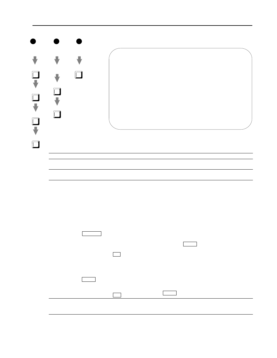
Counter Setup
or Monitor
or BT Data
Ladder Editor
Main Menu
Cursor to
BT instruction
F4
Output Setup
or
a
b
c
or
F9
I/O Ovrview
F7
General Utility
F2
F10
Edit
I/O Edit
Choose one:
F2
Edit
F4
Output Setup
Ladder Editor
Main Menu