D-10, Reset total and overflow flags, Btr word descriptions – Rockwell Automation 1771-CFM,D17716.5.99 CONFIGURABLE FLOWMET User Manual
Page 84
Replace Your QRD Module
D–10
Publication 1771Ć6.5.99 - December 1995
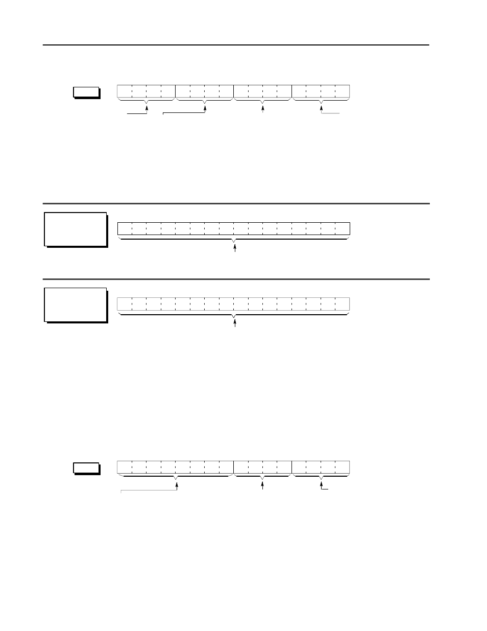
BTR Word Descriptions
15
14
13
12
11
10
09
08
07
06
05
04
03
02
01
00
Header must be 0001
Identifies the module as
a CFM (QRD) module.
word 1
15
14
13
12
11
10
09
08
07
06
05
04
03
02
01
00
Frequency Ċ indicates the calculated
frequency for the input channels.
15
14
13
12
11
10
09
08
07
06
05
04
03
02
01
00
0
0
0
1
.
word 5 (channel 0)
word 15 (channel 1)
word 25 (channel 2)
word 35 (channel 3)
word 2 (channel 1)
word 4 (channel 2)
word 6 (channel 3)
word 8 (channel 4)
word 5 (channel 0)
word 15 (channel 1)
word 25 (channel 2)
word 35 (channel 3)
word 3 (channel 1)
word 5 (channel 2)
word 7 (channel 3)
word 9 (channel 4)
Total Ċ the total counts registered
by the input channel.
Error Code displays error
code hex value:
0 = Valid Data
2 = Block Transfer Syntax Error:
BTW word 1, bits 08-15
any bit is ON (= 1)
Overflow Status
on if rollover has occurred
(counter has exceeded maximum
value of 32,767 and rolled over to 0).
This can only be reset by BTW
Overflow Reset.
b08 = Channel 1 b10 = Channel 3
b09 = Channel 2 b11 = Channel 4
VALUES: 0 = rollover has not occurred
1 = rollover has occurred
Overrange Alarm
on if the frequency is > 10.0kHz.
Frequency will be reported as 0.0Hz
and count will be reset to 0.
b04 = Channel 1 b06 = Channel 3
b05 = Channel 2 b07 = Channel 4
VALUES: 0 = frequency < overrange value
1 = frequency
≥
overrange value
RANGE: 0Ć10,000Hz
Frequency = 0 if Overrange Alarm = 1 (is ON).
RANGE: 0Ć32,767
Total = 0 if Overrange Alarm = 1 (is ON).
Reset Total and Overflow Flags
Any or all of the totalizers and overflow flags can be reset using a
BTW command sent to the CFM module from the PLC processor.
The BTW data word can be changed through the ladder logic, or by
editing the data table.
BTW Word Description
15
14
13
12
11
10
09
08
07
06
05
04
03
02
01
00
word 1
Overflow Reset
reset the overflow flag (these bits are
level sensitive upon receipt of BTW).
b04 = Channel 1 b06 = Channel 3
b05 = Channel 2 b07 = Channel 4
VALUES: 0 = not reset 1 = reset
Total Reset
➀
reset the total count
(these bits are level sensitive).
b00 = Channel 1 b02 = Channel 3
b01 = Channel 2 b03 = Channel 4
VALUES: 0 = not reset 1 = reset
➀
Resetting the total count will automatically reset its respective overflow flag(s).
Continuously doing BTW's with Total Reset = 1 (reset) will affect the accuracy of the frequency.
All of these bits must be OFF (= 0).
If any bit is ON, BTR word 1, bits 00Ć03
will display an error code of 2 (hex value).
0
0
0
0
.
0
0
0
0
.