Rockwell Automation 1771-CFM,D17716.5.99 CONFIGURABLE FLOWMET User Manual
Page 38
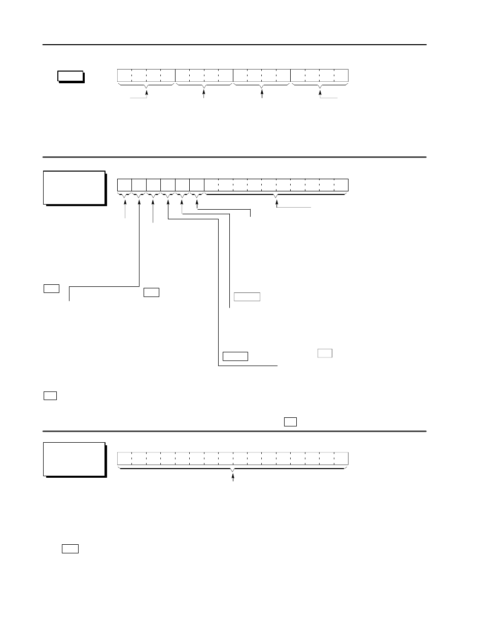
4–4
Configure the CFM Module
Publication 1771Ć6.5.99 - December 1995
Sampling Termination
if set, enables the input
sampling to be terminated
on either a time base only
(BTW 6) or a set number
of input pulses (BTW 7)
depending on which
condition arises first.
4 x High Hertz if set, the Highest Allowable
Frequency entry is multiplied by 4 to enable
entries > 32,767.
For example, to get a 100,000 peak allowable
frequency, you set this bit and enter 25,000 in the
word containing the Highest Allowable Frequency
(BTW 8, 18, 28 or 38).
Prover Type selects the type
of prover being used
(unidirectional or bidirectional):
0 = unidirectional (1 run, 2 switches)
1 = bidirectional (4 switch run)
15
14
13
12
11
10
09
08
07
06
05
04
03
02
01
00
Acceleration Calculation Time
calculates acceleration every Nth
frequency sample.
0 = acceleration rolling average over 5
samples
1Ć750 = number of frequency samples
(BTW 9 Acceleration Alarm Value must
0 0).
For example, if you place a value of 7
here, the CFM module:
a. stores the 1st frequency calculation
b. subtracts this calculation from the
8th frequency sample
c. divides this remainder by the time
between samples and places the
result in BTR 11, 20, 29 or 38
d. stores the 8th frequency sample
and waits for the 15th sample
all
T, NRT
all
HR
Bandwidth Limit if set, limits the minimum
frequency the CFM module is capable of reading
to 1/Minimum Frequency Sampling Time.
When 1: the worst case response time of the
module is decreased to approximately
2 x Minimum Frequency Sampling Time.
When 0: frequency range = 1Hz Ć 100kHz
(worst case response time can be 2s at
extremely low frequencies)
0 = full frequency range (1Hz Ć 100kHz)
1 = minimum frequency (1/Minimum Frequency Sampling Time)
all
Frequency in 10ths allows you
to select the precision of the
frequency returned in the BTR.
If set, the frequency is returned
with the LSD being in tenths,
while if 0, the LSD is in ones.
0 = frequency returned as 100, 123
1 = frequency returned as 100, 123.2
HR
15
14
13
12
11
10
09
08
07
06
05
04
03
02
01
00
Minimum Frequency Sampling Time specifies the minimum time the
CFM module spends to determine frequency (unless Number of Pulses to
Terminate Sampling is enabled in HighĆresolution Frequency mode, which may
allow the the input channel to end sampling earlier than the specified minimum).
Important: In Direction Sensor, this time is used to determine the maximum
sample time and the minimum frequency returned and does not
actually determine the time period for frequency sampling.
all
word 5 (channel 0)
word 15 (channel 1)
word 25 (channel 2)
word 35 (channel 3)
word 5 (channel 0)
word 15 (channel 1)
word 25 (channel 2)
word 35 (channel 3)
word 6 (channel 0)
word 16 (channel 1)
word 26 (channel 2)
word 36 (channel 3)
RANGE: 4ms Ć 1000ms (0 Ć 3 = DEFAULT)
DEFAULTS: HR, DS = 4ms / T, NRT = 100ms
Operating Mode for Channel 2
15
14
13
12
11
10
09
08
07
06
05
04
03
02
01
00
Operating Mode for Channel 0
Operating Mode for Channel 3
Operating Mode for Channel 1
0 = unused channel
1 = Totalizer
3 = HighĆresolution Frequency (channels 0 & 1 or 2 & 3)
➀
2 = Nonresettable Totalizer
4 = Direction Sensor (channels 0 & 1 or 2 & 3)
➀➁
word 4
Select a mode of operation on a per
channel basis by placing the shown
hex values in the proper bits:
➀
These modes are selected only via channel 0 or channel 2.
➁
If using both channels (0 & 1 and 2 & 3) for this mode, you cannot set sampling time for both = 4ms.
The maximum sampling time is:
< 2s Ċ if the Bandwidth Limit is not enabled and
a signal < 1 Hz is applied (sample time [
Minimum Frequency Sampling Time + 1/frequency input)
< 2 x the Minimum Frequency Sampling Time Ċ
if Bandwidth Limit is enabled and a very low input signal
frequency is applied (sample time [
Minimum Frequency Sampling Time + 1/frequency input)
Debounce Filtering
debounces the Gate
input for a period of 1s.
The first low to high transition
of the gate will cause the
CFM module to take
appropriate action (no other
transitions will be seen for 1s).
0 = OFF / 1 = ON
T, NRT