Make connections to the new wiring arm – Rockwell Automation 1771-CFM,D17716.5.99 CONFIGURABLE FLOWMET User Manual
Page 70
Replace Your QRC Module
C–6
Publication 1771Ć6.5.99 - December 1995
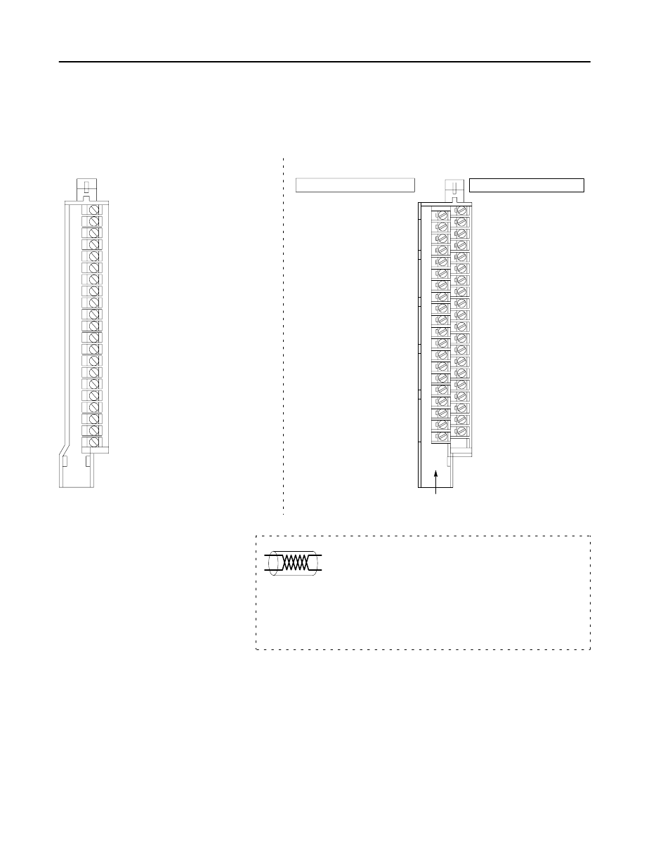
Connect your I/O devices to the 40-terminal field wiring arm
(cat. no. 1771-WN) shipped with the CFM module. Use the wiring
example on page C–7 for additional assistance on connecting
your devices.
F0 RET
F2 RET
Customer V DC #1 (5 to 40V)
Output 1
10689ĆI
F0 Input
F2 Input
Output 0
Customer V DC #1 RET (Outputs 0 &1 RET)
Even Numbered Terminals 2Ć40
Odd Numbered Terminals 1Ć39
NEW wiring arm (1771ĆWN)
OLD wiring arm (1771ĆWG)
1
2
3
4
5
6
7
8
9
10
11
12
13
14
15
16
17
18
19
20
21
18322
2
4
6
8
10
12
14
16
18
20
22
24
26
28
30
32
34
36
38
40
1
3
5
7
9
11
13
15
17
19
21
23
25
27
29
31
33
35
37
39
Overspeed outputs turned on within
1ms of frequency calculation.
(+) Magnetic pickĆup and shield Channel A
(-) Magnetic pickĆup
(+) Magnetic pickĆup and shield Channel B
(-) Magnetic pickĆup
Overspeed solid state relay Channel A
Overspeed solid state relay Channel B
Solid state relay common
actual wiring runs in this direction
The sensor cable must be shielded. The shield:
•
must extend the length of the cable, but be connected only
at the 1771 I/O chassis
•
must extend up to the point of termination
Important: The shield should extend to the termination point,
exposing just enough cable to adequately terminate the
inner conductors. Use heat shrink or another suitable
insulation where the wire exits the cable jacket.
Make Connections to the
New Wiring Arm