Through, Btw word descriptions – Rockwell Automation 1771-CFM,D17716.5.99 CONFIGURABLE FLOWMET User Manual
Page 37
4–3
Configure the CFM Module
Publication 1771Ć6.5.99 - December 1995
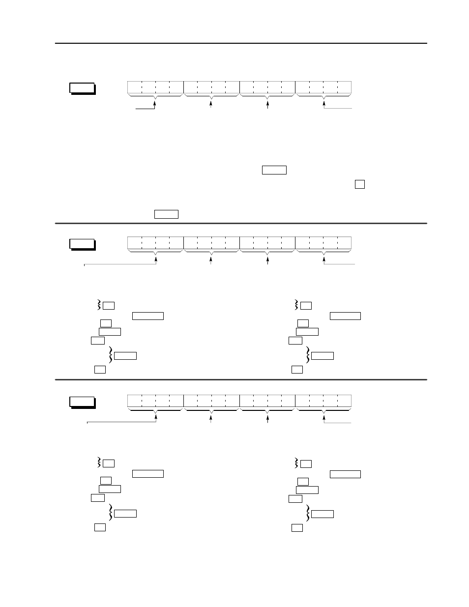
BTW Word Descriptions
Output 0 Trigger selects what
channel characteristic output 0
is triggered ON or OFF by placing
the shown hex values in these bits:
0 = Force OFF
1 = Frequency
2 = % of Fullscale Frequency
3 = Acceleration
4 = Total Value
5 = Direction
6 = Overflow
7 = Prover Running
8 = Prover Range
F = Force ON
Tie Output 1 to Channel ties
output 1 to operate according to
the state of a specific channel.
b08 = Counter 0 b10 = Counter 2
b09 = Counter 1 b11 = Counter 3
15
14
13
12
11
10
09
08
07
06
05
04
03
02
01
00
Total Reset resets the
total count for the
appropriate counter on a 0
to 1 transition.
Only occurs on a change
in bit state from a 0 to a 1.
b00 = Counter 0
b01 = Counter 1
b02 = Counter 2
b03 = Counter 3
Overflow Reset resets the
overflow status of the module for
the appropriate counter on a 0 to 1
transition. Only occurs on a
change in bit state from a 0 to a 1.
b04 = Counter 0 b06 = Counter 2
b05 = Counter 1 b07 = Counter 3
Prover Run Initialize initializes the
channel for prover inputs on the Gate.
Also resets Store Count Value
(BTR words 13 & 14). Only occurs on a
change in bit state from a 0 to a 1.
This bit should remain ON (= 1) until the
prover is done or until the prover run is
aborted.
b08 = Counter 0 b10 = Counter 2
b09 = Counter 1 b11 = Counter 3
If this bit is OFF (= 0), a low to high transition
of the Gate will store the current count in
Store Count Value (BTR words 13 & 14).
Header must be 0010.
Identifies the module as a
CFM module.
T
T, NRT
T, NRT
15
14
13
12
11
10
09
08
07
06
05
04
03
02
01
00
Tie Output 0 to Channel
ties output 0 to operate
according to the state
of a specific channel.
b00 = Counter 0
b01 = Counter 1
b02 = Counter 2
b03 = Counter 3
Output 1 Trigger selects what
channel characteristic output 1
is triggered ON or OFF by placing
the shown hex values in these bits:
0 = Force OFF
1 = Frequency
2 = % of Fullscale Frequency
3 = Acceleration
4 = Total Value
5 = Direction
6 = Overflow
7 = Prover Running
8 = Prover Range
F = Force ON
Tie Output 3 to Channel ties
output 3 to operate according to
the state of a specific channel.
b08 = Counter 0 b10 = Counter 2
b09 = Counter 1 b11 = Counter 3
15
14
13
12
11
10
09
08
07
06
05
04
03
02
01
00
Tie Output 2 to Channel
ties output 2 to operate
according to the state of
a specific channel.
b00 = Counter 0
b01 = Counter 1
b02 = Counter 2
b03 = Counter 3
word 3
word 2
word 1
0
0
1
0
all
T, NRT
DS
T, NRT
all
Output 3 Trigger selects what
channel characteristic output 3
is triggered ON or OFF by placing
the shown hex values in these bits:
0 = Force OFF
1 = Frequency
2 = % of Fullscale Frequency
3 = Acceleration
4 = Total Value
5 = Direction
6 = Overflow
7 = Prover Running
8 = Prover Range
F = Force ON
Output 2 Trigger selects what
channel characteristic output 2
is triggered ON or OFF by placing
the shown hex values in these bits:
0 = Force OFF
1 = Frequency
2 = % of Fullscale Frequency
3 = Acceleration
4 = Total Value
5 = Direction
6 = Overflow
7 = Prover Running
8 = Prover Range
F = Force ON
all
T, NRT, HR
all
T, NRT
DS
T, NRT
all
all
T, NRT, HR
all
T, NRT
DS
T, NRT
all
all
T, NRT, HR
all
T, NRT
DS
T, NRT
all
all
T, NRT, HR