Plcć2 family processor – Rockwell Automation 1771-CFM,D17716.5.99 CONFIGURABLE FLOWMET User Manual
Page 30
3–2
Edit Your Ladder Logic Program
Publication 1771Ć6.5.99 - December 1995
PLCĆ2 Family Processor
Important: The CFM module functions with reduced performance
in PLC-2 systems. Because the CFM module does not
support BCD and the PLC-2 processor is limited to
values of 4095 (12 bit binary), many values returned in
the BTR file may not provide meaningful data to the
PLC-2 processor.
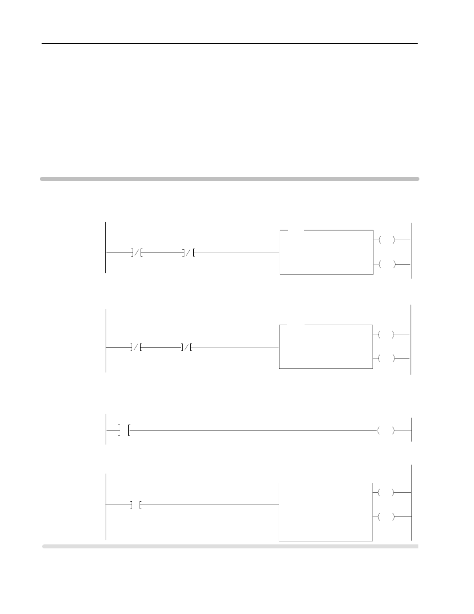
Use the following rungs to establish communication between the
CFM module and a PLC-2 processor.
EN
FILE TO FILE MOVE
Counter Addr:
Position:
File Length:
File A:
033
41
41
301-351
DN
File R:
Rate per Scan:
401Ć451
41
07
17
15
111
033
033
EN
DN
06
111
011
111
06
06
EN
BLOCK TRANSFER READ
Data Addr:
Module Addr:
Block Length:
030
110
00
DN
File:
301-400
07
111
011
111
07
07
BTR
BLOCK TRANSFER WRITE
Data Addr:
Module Addr:
Block Length:
031
110
00
File:
201-300
PUT
032
G
032
0
0
BTW
FFM
Rung M:1
The CFM module is located in rack 1, I/O group 1, slot 0. The data address 030 must be among the first available timer/
counter address used for block transfer. The default block length of 0 will return 41 words starting at address 301. If a block
length other than 0 is desired, the BTR and BTW must not both be enabled in the same scan.
CFM BTR Data Address
CFM BTR
Done Bit
CFM BTW
Enable Bit
06
011
Rung M:2
The CFM module is located in rack 1, I/O group 1, slot 0. The data address 031 must be among the first available timer/
counter address used for block transfer. The default length of 0 will send 60 words starting at address 201. If a block length
other than 0 is desired, the BTR and BTW must not both be enabled in the same scan.
CFM BTW
Done Bit
CFM BTR
Enable Bit
07
011
Rung M:3
This rung is used to place a zero between the first available timer counters used for all block transfers and those used
throughout the rest of the program.
Rung M:4
This rung uses the BTR done bit to trigger a FFM that moves the CFM status to a buffered data file. The program should
access all CFM data from the file starting at 401.
CFM BTR
Done Bit
PLCĆ2 Processor
Program Example
UNUSED
must be = 0
UNUSED
must be = 0