Resume normal operation, Edit your ladder logic program – Rockwell Automation 1771-CFM,D17716.5.99 CONFIGURABLE FLOWMET User Manual
Page 72
Replace Your QRC Module
C–8
Publication 1771Ć6.5.99 - December 1995
The CFM module, configured for QRC module emulation, operates
as a QRC module. Use the following section for reference on how
the CFM (QRC) module operates.
Important: The CFM module has 50mV sensitivity. This is
different than the QRC module, which had 20 to
300mV sensitivity, depending on the hardware level.
Edit Your Ladder Logic Program
To initiate communication between the CFM module and your
PLC processor, you must enter block transfer instructions into your
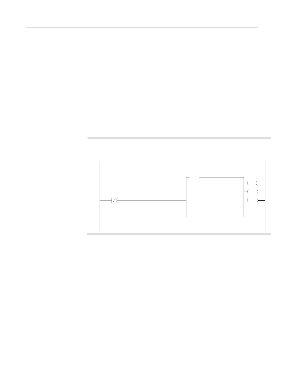
ladder logic program. Enter the following rung to establish
communication between the CFM module and your PLC processor.
EN
BTR
BLOCK TRANSFER READ
Rack
Group
Slot
Data File
00
1
0
N23:1
Length
Control Block
0
N23:60
N23:60
15
DN
ER
The CFM (QRC) module is located in rack 0, I/O group 1, slot 0. There are 3 words of data sent from the CFM (QRC)
module to the PLC processor. This data is stored at N23:1. The BTR control file, starting at n23:60, is 5 words long.
CFM (QRC)
BTR EN Bit
CFM (QRC) BTR
CONTROL FILE
PLCĆ5 Program Example
N
Continuous
Block transfer instructions use one binary file in a
data table section for module location and other
related data. The block transfer data file stores
data that you want transferred from the CFM
(QRC) module (when programming a BTR).
The address of the block transfer data files are
stored in the block transfer control file.
The programming terminal prompts you to create
a control file when a block transfer instruction is
being programmed. A different block transfer
control file is required for every module.
Resume Normal Operation