Configuration data file – Rockwell Automation 1769-XXXX Compact I/O Modules User Manual
Page 88
88
Rockwell Automation Publication 1769-IN088A-EN-P - February 2011
Chapter 3 I/O Memory Mapping
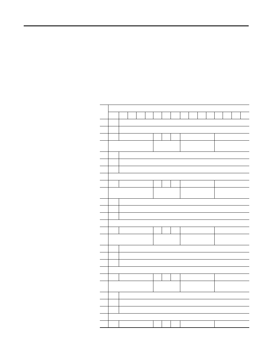
Configuration Data File
The manipulation of bits from this file is normally done with programming
software, such as RSLogix 500, RSLogix 5000, or RSNetWorx for DeviceNet,
during initial configuration of the system. In that case, graphical screens provided
by the programming software simplify configuration.
Some systems, like the 1769-ADN DeviceNet adapter system, also allow the bits
to be altered as part of the control program using communication rungs. In that
case, it is necessary to understand the bit arrangement.
Wo
rd
Bit Position
15
14
13
12
11
10
09
08
07
06
05
04
03
02
01
00
0
0
Real Time Sample Value
1
ETS
Reserved
2
EC
Reserved
EA
AL
EI
(1)
Reserved
Input Filter Sel Ch0
3
Reserved
Input Data
Format Ch0
Reserved
Input Type/Range
Select Ch0
4
SGN
Process Alarm High Data Value Channel 0
5
SGN
Process Alarm Low Data Value Channel 0
6
SGN
Alarm Dead Band Value Channel 0
7
Reserved
8
EC
Reserved
EA
AL
EI
(1)
Reserved
Input Filter Sel Ch1
9
Reserved
Input Data
Format Ch1
Reserved
Input Type/Range
Select Ch1
10
SGN
Process Alarm High Data Value Channel 1
11
SGN
Process Alarm Low Data Value Channel 1
12
SGN
Alarm Dead Band Value Channel 1
13
Reserved
14
EC
Reserved
EA
AL
EI
(1)
Reserved
Input Filter Sel Ch2
15
Reserved
Input Data
Format Ch2
Reserved
Input Type/Range
Select Ch2
16
SGN
Process Alarm High Data Value Channel 2
17
SGN
Process Alarm Low Data Value Channel 2
18
SGN
Alarm Dead Band Value Channel 2
19
Reserved
20
EC
Reserved
EA
AL
EI
(1)
Reserved
Input Filter Sel Ch3
21
Reserved
Input Data
Format Ch3
Reserved
Input Type/Range
Select Ch3
22 SGN
Process Alarm High Data Value Channel 3
23
SGN
Process Alarm Low Data Value Channel 3
24
SGN
Alarm Dead Band Value Channel 3
25
Reserved
26
EC
Reserved
EA
AL
EI
(1)
Reserved
Input Filter Sel Ch4