1769-of4vi, Input data file, Output data file – Rockwell Automation 1769-XXXX Compact I/O Modules User Manual
Page 139: Input data file output data file
Rockwell Automation Publication 1769-IN088A-EN-P - February 2011
139
I/O Memory Mapping Chapter 3
1769-OF4VI
The following I/O memory mapping lets you configure the 1769-OF4VI
module.
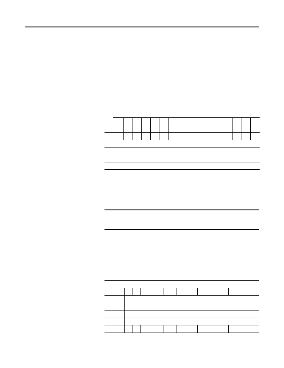
Input Data File
For each module, slot
x, input data file words 2…5 contain the state of the
module’s output data (output data echo) file words 0…3. During normal
operation, these input words represent the analog values that the outputs are
directed to by the control program.
• S = General status (over-range, under-range, or low/high clamp exceeded).
• H = Output held bit.
• U = Under-range (or low-clamp exceeded) alarm.
• O = Over-range (or high-clamp exceeded) alarm.
Output Data File
For each module, slot
x, words 0…3 in the output data file contain the channel
0…channel 3 output data. Word 4 is used to unlatch any alarm condition that has
been latched. Refer to your module user manual for additional details.
Wo
rd
Bit Position
15
14
13
12
11
10
9
8
7
6
5
4
3
2
1
0
0
S3
S2
S1
S0
1
H3
U3
O3
H2
U2
O2
H1
U1
O1
H0
U0
O0
2
Channel 0 Data Value
3
Channel 1 Data Value
4
Channel 2 Data Value
5
Channel 3 Data Value
IMPORTANT
The output module input data file reflects the analog output data echo of
the module, not necessarily the electrical state of the output terminals. It
does not reflect shorted or open outputs.
Wo
rd
Bit Position
15
14
13
12
11 10 9
8
7
6
5
4
3
2
1
0
0
SGN
Analog Output Data Channel 0
1
SGN
Analog Output Data Channel 1
2
SGN
Analog Output Data Channel 2
3
SGN
Analog Output Data Channel 3
4
UU3 UO3 UU2 UO2 UU1 UO1 UU0 UO0