Output data file – Rockwell Automation 1769-XXXX Compact I/O Modules User Manual
Page 62
62
Rockwell Automation Publication 1769-IN088A-EN-P - February 2011
Chapter 3 I/O Memory Mapping
• Ox = Word 5, bits 0 and 1 provide over-range indication for output
channels 0 and 1. These bits can be used in the control program for error
detection. When set to 1, the bits signal that the output signal is outside
the normal operating range. However, the module continues to convert
analog data to the maximum full-range value. When the over-range
condition is cleared, the bits automatically reset (0).
• Ex = When set (1), this bit indicates that invalid data has been set in the
output data bits 0 through 6 or the sign bit (15). For example, the value
sent by the controller is outside the standard output range or increment,
such as 128, 256.
• Hx = Hold Last State bits. When set (1), these bits indicate that the
channel is in a Hold Last State condition.
• Words 6 and 7 = These words reflect the analog output data echo of the
analog value being converted by the digital/analog converter, not
necessarily the electrical state of the output terminals. They do not reflect
shorted or open outputs.
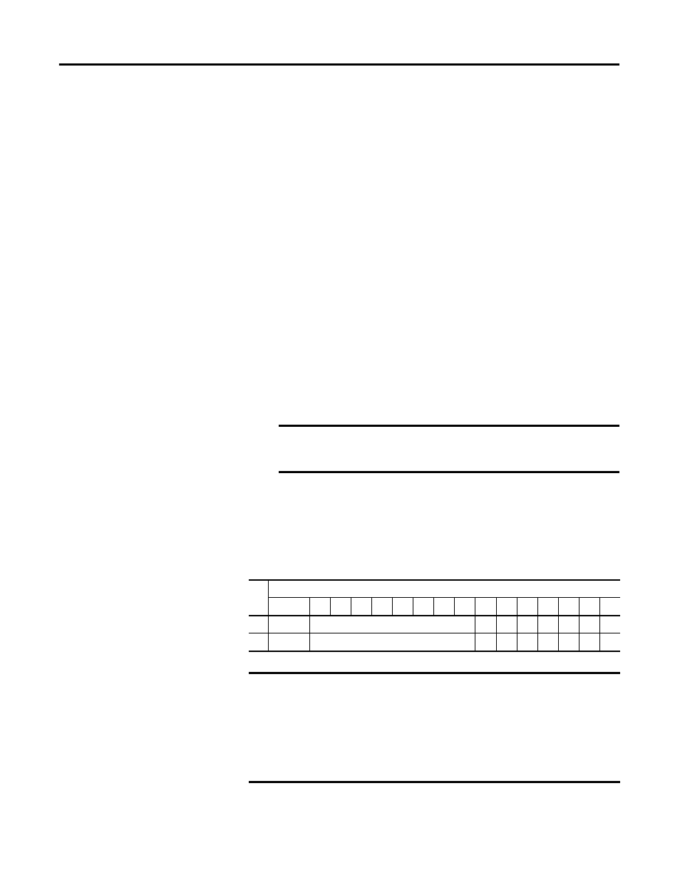
Output Data File
The output data file applies only to output data from the module as shown in the
table below.
TIP
Under-range indication is not provided because zero is a valid
number.
IMPORTANT
It is only important to use the loopback function of input words 6
and 7 if the controller supports the Program mode or Fault mode
functions, and if it is configured to use them.
Wo
rd
Bit Position
15
14
13
12
11
10
9
8
7
6
5
4
3
2
1
0
0
SGN
Analog Output Data Channel 0
0
0
0
0
0
0
0
1
SGN
Analog Output Data Channel 1
0
0
0
0
0
0
0
IMPORTANT
Bits 0 through 6 and Bit 15 of output data words 0 and 1 should always
be set to zero in your control program. If they are not set to 0, the invalid
data flag (Ex) will be set for that channel. However, the channel will
continue to operate with the previously converted value. If a MVM (Move
with Mask) instruction is used with a mask of 7F80 (hexidecimal) to move
data to the output words, writing to bits 0 through 6 and bit 15 can be
avoided.