Configuration file – Rockwell Automation 1769-XXXX Compact I/O Modules User Manual
Page 185
Rockwell Automation Publication 1769-IN088A-EN-P - February 2011
185
I/O Memory Mapping Chapter 3
The bits are defined as follows:
• Tx = Transmit
• Rx = Receive
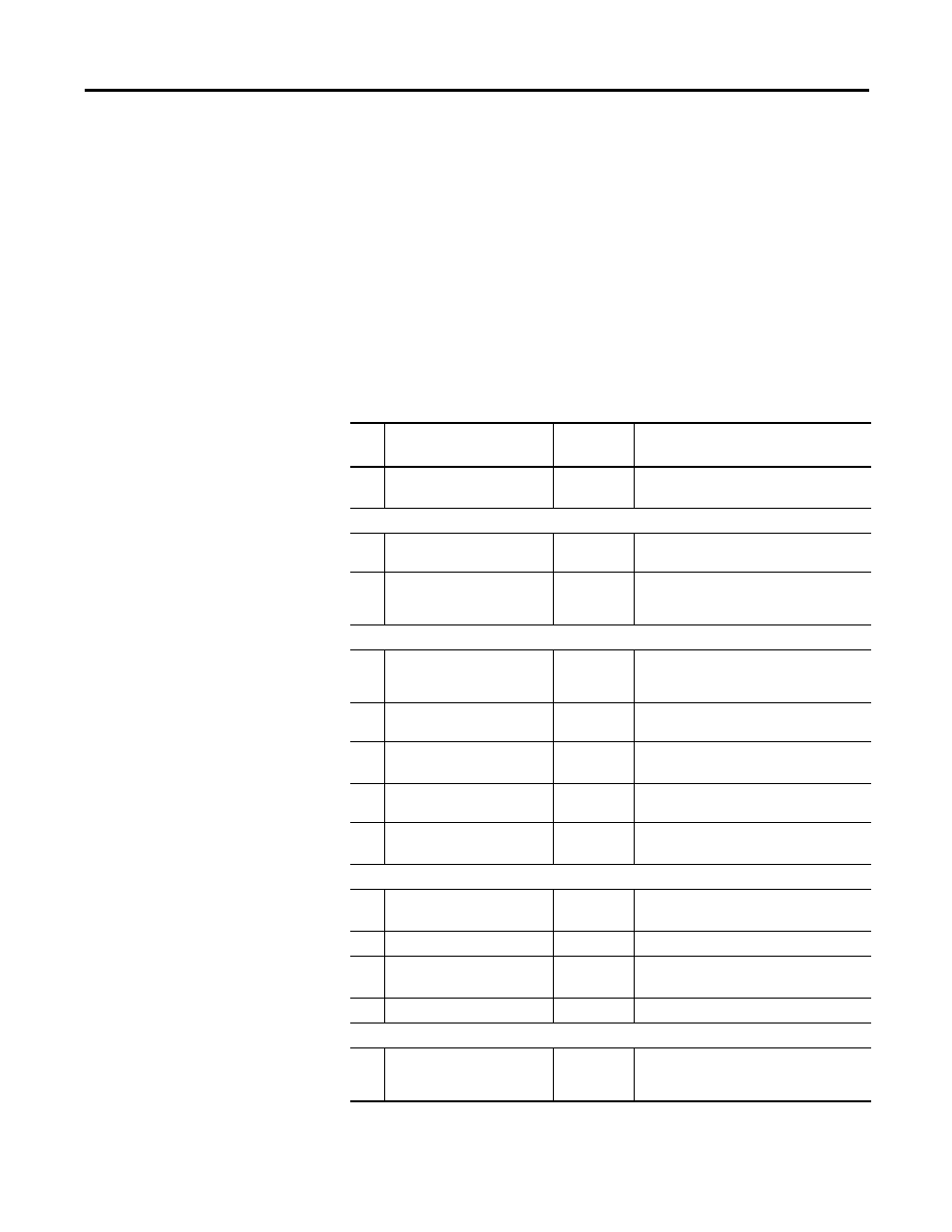
Configuration File
The 1769-ASCII module supports a configuration assembly that is accessible
through the Assembly Object (Class 4), Instance 102. The configuration
assembly is 31 words. The addresses assume a 16-bit data structure where all 16-
bit values are INT
(1)
. The least significant word occupies the smaller byte
addresses.
(1) INT = Integer range of -32768 to +32767 decimal, 0000 to FFFF hexadecimal.
Wo
rd
Description
Values
Valid Data Values
0
Data Buffer Mode
0…1
0 = alternate mode
1 = simultaneous mode
Channel 0
1
Serial Character Framing
0…8
0 = 7N2, 1 = 7E1, 2 = 7O1, 3 = 8N1, 4 = 8N2,
5 = 8E1, 6 = 8O1, 7 = 7E2, 8 = 7O2
2
Serial Port Speed
0…7
0 = 9600, 1 = 1200, 2 = 2400, 3 = 4800,
4 = 19200, 5 = 38400, 6 = 57.6k, 7 = 115.2k
(half-duplex only)
Serial Port Receive Data
3
Max Number of Receive
Characters
0…200
In Simultaneous mode, the total number of
channel 0 characters plus channel 1
characters cannot exceed 200.
4
Receive Record Start Mode
0…2
0 = ignore, 1 = exclude, 2 = include start
delimiter
5
Receive Start Delimiter
(1)
0…127/255
0…0x7f (0…127) for 7-bit data
0…0xff (0…255) for 8-bit data
6
Receive Record End Mode
0…2
0 = ignore, 1 = exclude, 2 = include end
delimiter
7
Receive End Delimiter
(1)
0…127/255
0…0x7f (0…127) for 7-bit data
0…0xff (0…255) for 8-bit data
Module Production Data
8
Pad Character
(1)
0…127/255
0…0x7f (0…127) for 7-bit data
0…0xff (0…255) for 8-bit data
9
Receive Swap Mode
0…2
0 = disabled, 1 = 16-bit, 2 = 32-bit
10
Master Handshake Mode
0…1
0 = master/slave handshake,
1 = produce immediate
11
Message Time Out
0…65535
0 = none, 1 to 65535 ms
Serial Port Transmit Data
12
Max Number of Transmit
Characters
0…200
In Simultaneous mode, the total number of
channel 0 characters plus channel 1
characters cannot exceed 200.