Rockwell Automation 1785-L20C_L40C, D17856.5.14 ControlNet PLC-5 Programmable Controllers User Manual User Manual
Page 13
Chapter 1
Installing Your ControlNet PLCĆ5 Processor
1-5
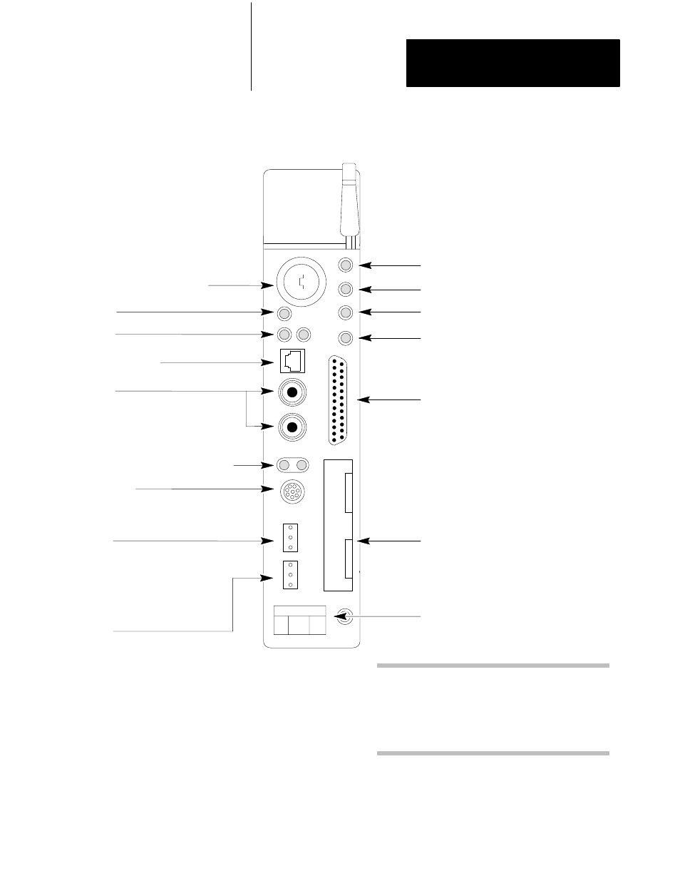
Figure 1.2
PLCĆ5/40C Processor Front Panel
Battery Status Indicator
(Red)
Processor RUN/FAULT Status Indicator
(Green/Red)
Force Status Indicator
(Amber)
Channel 0 Communication ACTIVE/FAULT
Status Indicator
(Green/Red)
Memory Module Space
Battery Compartment
Use this port with ASCII or DF1 fullĆduplex, halfĆ
duplex master, and halfĆduplex slave protocols.
The port's default configuration supports processor
programming:
KeyswitchĊselects processor mode
Channel 0
Serial PortĊ25Ćpin DĆshell; supports standard EIA
RSĆ232C and RSĆ423; is RSĆ422A compatible
➀
DH+ Programming Terminal Connection
to Channel 1A
8Ćpin miniĆDIN, parallel with 3Ćpin connectors
of Channel 1A; use only when Channel 1A is
configured for DH+ communications
•
one stopĆbit
•
BCC error check
•
no handshaking
•
DF1 pointĆtoĆpoint
•
2400 bps
•
no parity
Channel 2
ControlNet Redundant Media PortsĊ
BNC; dedicated
➀
Channel 0 is optically coupled (provides high electrical
noise immunity) and can be used with most RSĆ422A
equipment as long as:
•
termination resistors are not used
•
the distance and transmission rate are reduced to
comply with RSĆ423 requirements
ControlNet Network Access Port
(NAP)ĊRJ45 connector
Channel 1 Status Indicators (Green/Red)
Channel 1A
3 pin; default is DH+; configurable for:
•
remote I/O scanner
•
remote I/O adapter
•
DH+ communication
•
unused
Channel 1B
3 pin; default is remote I/O scanner;
configurable for:
•
remote I/O scanner
•
remote I/O adapter
•
DH+ communication
•
unused
Channel 2 ControlNet Status Indicators
(Green/Red)
ControlNet I/O Status Indicator
(Green/Red)