Rockwell Automation 1336 8A-48A Fiber Industry User Manual
Page 99
5–33
Programming
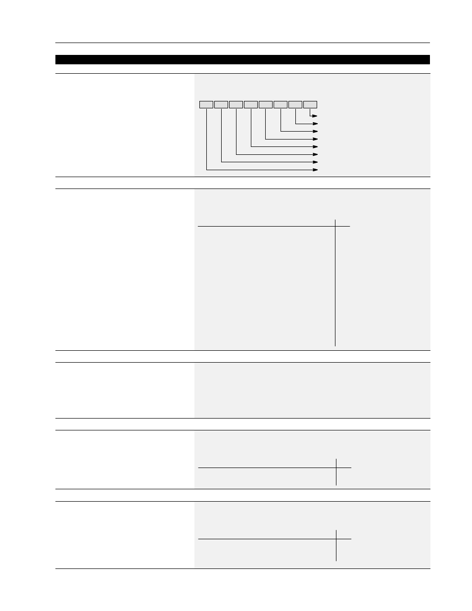
[Input Status]
This parameter displays the on/off status of inputs
1-8 at TB3 if an optional interface card is installed.
With a Series A (version 3.0) or Series B HIM, a
Status description (bit ENUM) is displayed on line 1.
Parameter Number
55
Parameter Type
Read Only
Bit 7
Bit 6
Bit 5
Bit 4
Bit 3
Bit 2
Bit 1
Bit 0
Input 1 – TB3-19
Input 2 – TB3-20
Input 4 – TB3-23
Input 3 – TB3-22
Input 5 – TB3-24
Input 6 – TB3-26
Input 8 – TB3-28
Input 7 – TB3-27
[Freq Source]
This parameter displays the frequency source
currently commanding the drive.
Parameter Number
62
Parameter Type
Read Only
Factory Default
None
Units
Display Drive
“Adapter 1” 6
“Adapter 2” 7
“Adapter 3” 8
“Adapter 4” 9
“Adapter 5” 10
“Adapter 6” 11
“Preset 1-7” 12-18
“Iso Analog” 19
“Jog Sel” 20
“Use Last” 0
“Remote Pot” 1
“0-10 Volt” 2
“4-20 mA” 3
“Pulse Ref” 4
Unused 5
[Freq Command]
This parameter displays the frequency that the drive
is commanded to output. This command may come
from any one of the frequency sources selected by
[Freq Select 1] or [Freq Select 2].
Parameter Number
65
Parameter Type
Read Only
Display Units / Drive Units
0.01 Hertz / 32767 = Maximum Freq Forward
Factory Default
None
Minimum Value
–400.00 Hz
Maximum Value
+ 400.00 Hz
[Drive Direction]
This parameter displays the commanded running
direction.
Parameter Number
69
Parameter Type
Read Only
Factory Default
None
Units
Display Drive
“Forward” 0
“Reverse” 1
[Stop Mode Used]
This parameter displays the active stop mode.
Parameter Number
26
Parameter Type
Read Only
Factory Default
None
Units
Display Drive
“Coast” 0
“DC Brake” 1
“Ramp” 2
Diagnostics