Diagnostics [drive status, Drive alarm, Latched alarms – Rockwell Automation 1336 8A-48A Fiber Industry User Manual
Page 98
5–32
Programming
This group of parameters contains values that can be helpful in explaining the operation of
the drive. Drive status, direction, control and alarm conditions as well as drive ratings are
included.
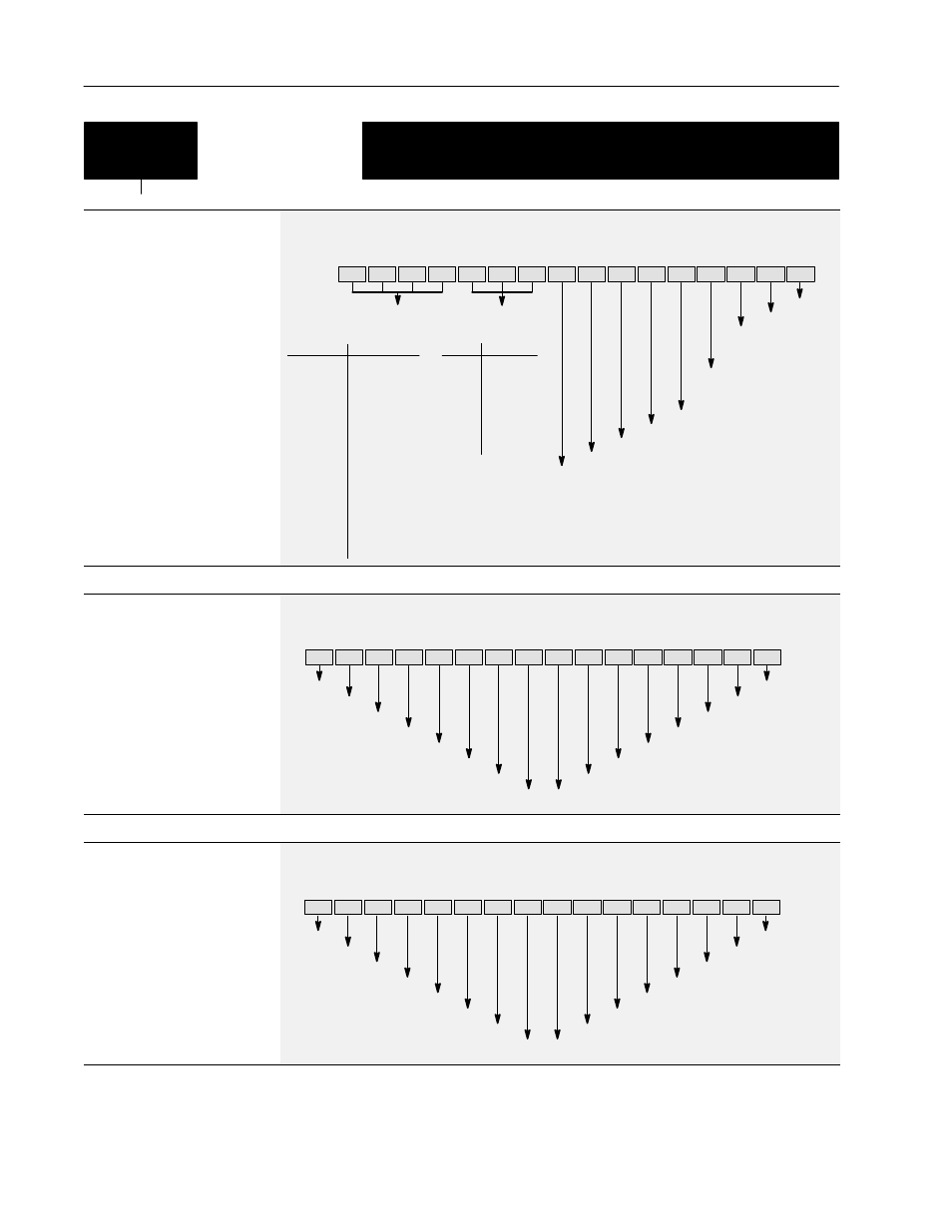
Diagnostics
[Drive Status]
This parameter displays the actual
operating condition in binary format.
Bits 0-7 are displayed on lower half
of line 2 on HIM display, while, bits
8-15 are displayed on the upper half
of line 2.
With a Series A (version 3.0) or
Series B HIM, a Status description
(bit ENUM) is displayed on line 1.
Parameter Number
59
Parameter Type
Read Only
Enabled
Running
Command Direction
Actual Direction
Accelerating
Decelerating
Faulted
At Speed
Bit 15
Bit 13 Bit 12 Bit 11 Bit 10 Bit 9
Bit 8
Bit 7
Bit 6
Bit 5
Bit 4
Bit 3
Bit 2
Bit 1
Bit 0
Alarm
0 = Reverse
1 = Forward
0 = Reverse
1 = Forward
Reference
ID
Local
Adapter ID
Reference
15 14 13 12
Freq Select 1
0
0
0
0
Preset Freq 1
0
0
0
1
Preset Freq 2
0
0
1
0
Preset Freq 3
0
0
1
1
Preset Freq 4
0
1
0
0
Preset Freq 5
0
1
0
1
Preset Freq 6
0
1
1
0
Preset Freq 7
0
1
1
1
Freq Select 2
1
0
0
0
Adapter 1
1
0
0
1
Adapter 2
1
0
1
0
Adapter 3
1
0
1
1
Adapter 4
1
1
0
0
Adapter 5
1
1
0
1
Adapter 6
1
1
1
0
Jog Frequency 1
1
1
1
Local
11 10 9
TB3
0
0
0
1
0
0
1
2
0
1
0
3
0
1
1
4
1
0
0
5
1
0
1
6
1
1
0
Unused
1
1
1
Bit 14
[Drive Alarm]
This parameter displays which
alarm condition is present when bit
6 of [Drive Status] is high
(set to 1). Refer to Chapter 6 for
further alarm information.
With a Series A (version 3.0) or
Series B HIM, a Status description
(bit ENUM) is displayed on line 1.
Parameter Number
60
Parameter Type
Read Only
Bus Charging
Regenerating Current Limit
Regenerating Voltage Limit
Line Loss In Progress
Motor Stalled
Ground Warning
Bit 15
Bit 13 Bit 12 Bit 11 Bit 10 Bit 9
Bit 8
Bit 7
Bit 6
Bit 5
Bit 4
Bit 3
Bit 2
Bit 1
Bit 0
Sync Loss
Bit 14
Hardware Current Limit
Motoring Current Limit
Unused
Unused
Voltage Check
Heatsink Temp
Auxiliary Input
4-20 mA Loss
Overcurrent
[Latched Alarms]
This parameter “stores” the [Drive
Alarm] indications (see above). Bits
will remain set (high/1), even if the
alarm condition no longer exists.
The bit(s) must be programmed to
zero to release the stored
indications.
With a Series A (version 3.0) or
Series B HIM, a Status description
(bit ENUM) is displayed on line 1.
Parameter Number
205
Parameter Type
Read Only
Bus Charging
Regenerating Current Limit
Regenerating Voltage Limit
Line Loss In Progress
Motor Stalled
Ground Warning
Bit 15
Bit 13 Bit 12 Bit 11 Bit 10 Bit 9
Bit 8
Bit 7
Bit 6
Bit 5
Bit 4
Bit 3
Bit 2
Bit 1
Bit 0
Sync Loss
Bit 14
Hardware Current Limit
Motoring Current Limit
Unused
Unused
Voltage Check
Heatsink Temp
Auxiliary Input
4-20 mA Loss
Overcurrent