Setup [input mode, Freq select 1, Accel time 1 – Rockwell Automation 1336 8A-48A Fiber Industry User Manual
Page 74
5–8
Programming
This group of parameters defines basic operation and should be programmed before initial
use of the drive. For advanced programming and information on specific parameters, refer
to the flow chart on pages 5–2 & 5–3.
Setup
[Input Mode]
This parameter selects the functions of inputs 1-8 at
TB3 when an optional interface card is installed.
Refer to Input Mode Selection figure in Chapter 2.
This parameter cannot be changed while the drive is
running. Power to the drive must be cycled before
any changes will affect drive operation.
Parameter Number
21
Parameter Type
Read and Write
Display Units / Drive Units
Mode Number / Selection
Factory Default
1
Minimum Value
1
Maximum Value
16
[Freq Select 1]
This parameter controls which of the frequency
sources is currently supplying the
[Freq Command] to the drive unless
[Freq Select 2] or [Preset Freq 1-7] is selected.
Refer to the Speed Select Input Table in Chapter 2.
Parameter Number
5
Parameter Type
Read and Write
Factory Default
“Adapter 1”
Units
Display Drive
“Adapter 1” 6
“Adapter 2” 7
“Adapter 3” 8
“Adapter 4” 9
“Adapter 5” 10
“Adapter 6” 11
“Preset 1-7” 12-18
“Iso Analog” 19
“Jog Sel” 20
“Use Last” 0
“Remote Pot” 1
“0-10 Volt” 2
“4-20 mA” 3
“Pulse Ref” 4
Refer to [Pulse/Enc Scale] Scale Value
Unused 5
If selected, causes a Hertz Sel Fault
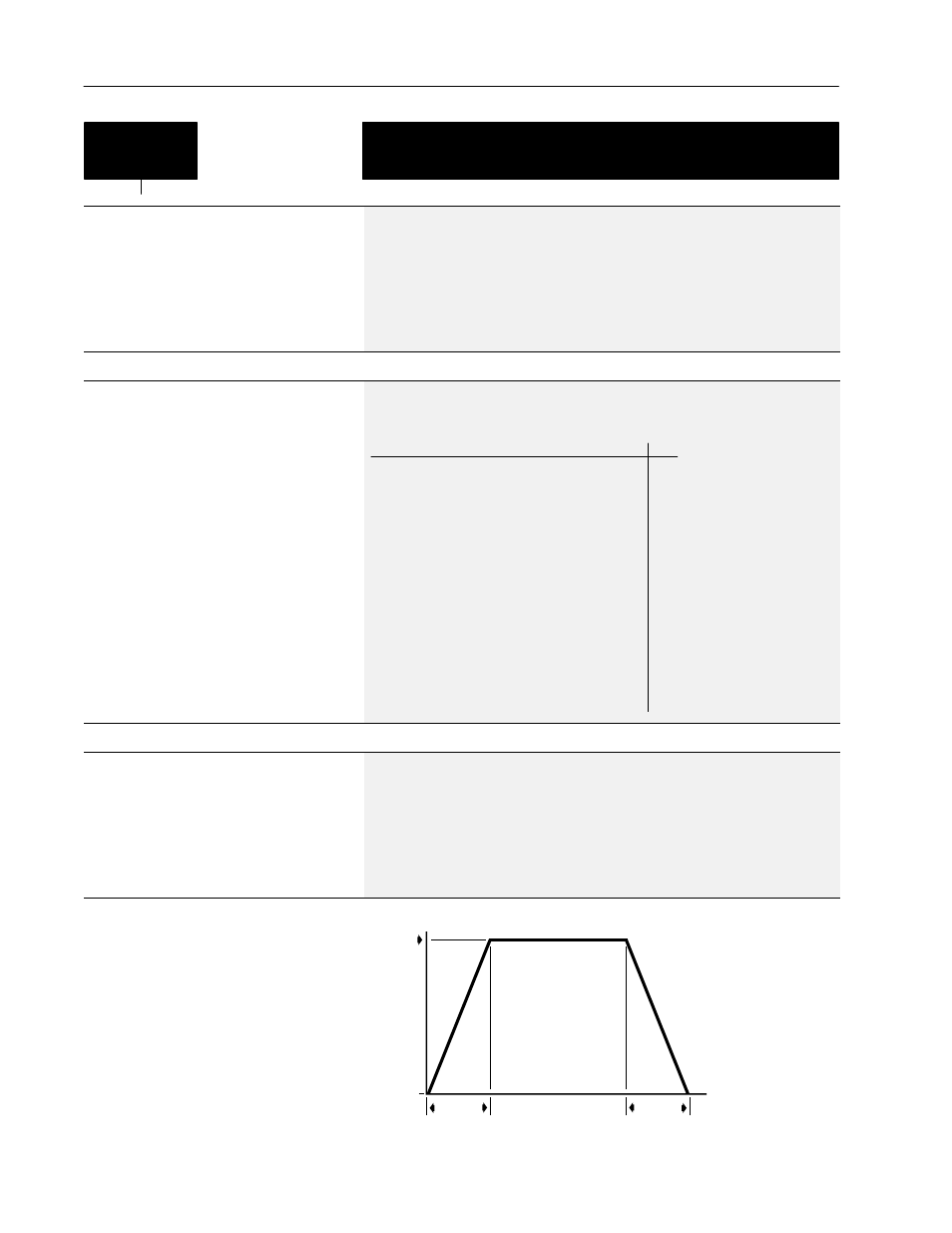
[Accel Time 1]
This value determines the time it will take the drive
to ramp from 0 Hz to [Maximum Freq]. The rate
determined by this value and [Maximum Freq] is
linear unless [S Curve Enable] is “Enabled.” It
applies to any increase in command frequency
unless [Accel Time 2] is selected.
Parameter Number
7
Parameter Type
Read and Write
Display Units / Drive Units
0.1 Second / Seconds x 10
Factory Default
10.0 Sec
Minimum Value
0.0 Sec
Maximum Value
6000.0 Sec
Accel/Decel Time
Speed
0
Time
Constant Speed
Accel Time
Decel Time
0
Ac
ce
le
ra
tio
n
De
ce
le
ra
tio
n