Rockwell Automation 1336 8A-48A Fiber Industry User Manual
Page 109
5–43
Programming
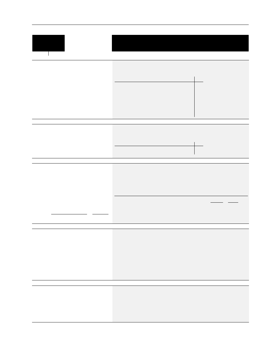
This group of parameters contains all the parameters necessary to activate encoder feed-
back for closed loop operation.
Encoder
Feedback
[Speed Control]
This parameter selects the type of speed modulation
active in the drive.
This parameter cannot be changed while the drive is
running.
Important: If encoder feedback closed loop speed
regulation is required, “Encoder Fdbk” must be
selected.
Parameter Number
77
Parameter Type
Read and Write
Factory Default
“No Control”
Units
Display Drive
“No Control” 0
Frequency regulation
“Slip Comp” 1
Slip compensation
“Speed Droop” 2
Negative slip compensation
“PLL” 3
Phase lock loop
“Encoder Fdbk” 4
Encoder feedback–closed loop
“Droop + Reg” 5
Enc. fdbk.–closed loop w/ active droop
“P Jump” 6
Traverse function
[Encoder Type]
This parameter contains the feedback encoder signal
type. The drive can accept single-ended, single-
channel (Pulse) or differential (Quadrature) signals.
This cannot be changed while drive is running.
Parameter Number
152
Parameter Type
Read and Write
Factory Default
“Pulse”
Units
Display Drive
“Pulse” 0
“Quadrature” 1
[Pulse/Enc Scale]
This parameter contains the scaling factor for both
pulse train inputs (TB2-7, 8) and encoder feedback
speed regulation (TB3 terminals 31-36).
1. Encoder Feedback Operation
Enter actual encoder pulses per revolution
2. Pulse Train Input
Scale
Factor
Incoming Pulse Rate (Hz)
Desired Command Freq.
Motor Poles
2
x
=
Parameter Number
46
Parameter Type
Read and Write
Display Units / Drive Units
Factor / Pulses per Rev
Factory Default
64 PPR
Minimum Value
1
Maximum Value
4096
Pulse Train Example:
4 Pole Motor, 60 Hz = Max. Speed.
The 1336–MOD–N1 option outputs 64 Hz/Hz.
At full analog reference, the pulse output will
be 60 Hz x 64 Hz/Hz = 3840 pulses/sec.
Pulse/Enc Scale
3840 Hz
60 Hz
4 Poles
2
= 128
This value will create a command frequency of
60 Hz for full analog reference to the option.
=
x
[Maximum Speed]
This parameter sets the output frequency at full
frequency reference for:
1. Encoder feedback speed regulation.
2. All analog inputs to TB2 (remote pot, 0-10V &
0-20 mA).
NOTE: [Maximum Freq.] must be raised to allow
operation or modulation above [Maximum Speed].
Parameter Number
151
Parameter Type
Read and Write
Display Units / Drive Units
1 Hertz / Hertz x 1
Factory Default
400 Hz
Minimum Value
0 Hz
Maximum Value
400 Hz
[Motor Poles]
This parameter contains the number of motor
magnetic poles. This value translates output
frequency into actual motor RPM during closed loop
operation. It is calculated from
[Motor NP Hertz] and [Motor NP RPM].
Parameter Number
153
Parameter Type
Read Only
Display Units / Drive Units
1 Poles / Poles