Chapter 3, Using front display, Indicators and controls – SATEC PM130 PLUS Manual User Manual
Page 42: Device diagnostics, Numeric led display, Chapter 3 using front display, 1 indicators and controls device diagnostics
Chapter 3 Using
F R O N T D I S P L A Y
Indicators
A N D C O N T R O L S
42
PM130 PLUS Powermeter Series
Chapter 3 Using Front Display
This chapter provides PM130 PLUS Power meter series front panel
information and operating procedures.
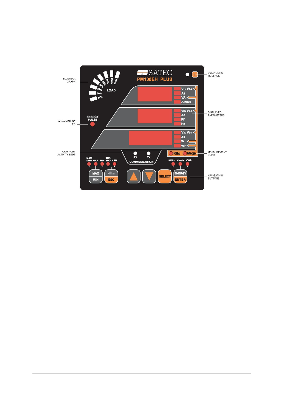
Figure 3-1: PM130 PLUS Unit
3.1 Indicators and Controls
Device Diagnostics
After applying power to the meter, a one-digit start-up diagnostic code is
shown for 1 second on all LEDs. Code 8 indicates a normal power-up
sequence. You can observe the list of device diagnostic codes recorded
during restart and meter operation via the
When the meter records a diagnostic message, the diagnostic “i” LED
flashes until you reset the device diagnostics via the
. The
diagnostic LED can be disabled or enabled through the display setup (see
Numeric LED Display
The meter has a simple user interface that allows you to view numerous
measurement parameters by scrolling through different display pages. The
numeric LED display shows up to three parameters at a time. Small
rectangular or round LEDs at the right and below the display indicate the
displayed parameters and their measurement units.
The display layout may change depending on the meter type and mode of
operation.
There are three modes of display operation:
Data display
Status display
Programming mode display.