Zero the spool position signal, Zero the spool position signal 99 – MTS Series 793 User Manual
Page 99
How to Perform Advanced Tuning Techniques
MTS Series 793 Tuning and Calibration
Tuning Procedures
99
B. In the Inputs panel, click the Adjustment tab.
C. In the Adjustment tab, increase the P Gain.
13. Tune the inner loop.
Standalone FlexTest SE Controllers: Setup > Output > Inner Loop
Automated Controllers: In the Station Setup window’s Drive panel, click
the Inner Loop tab.
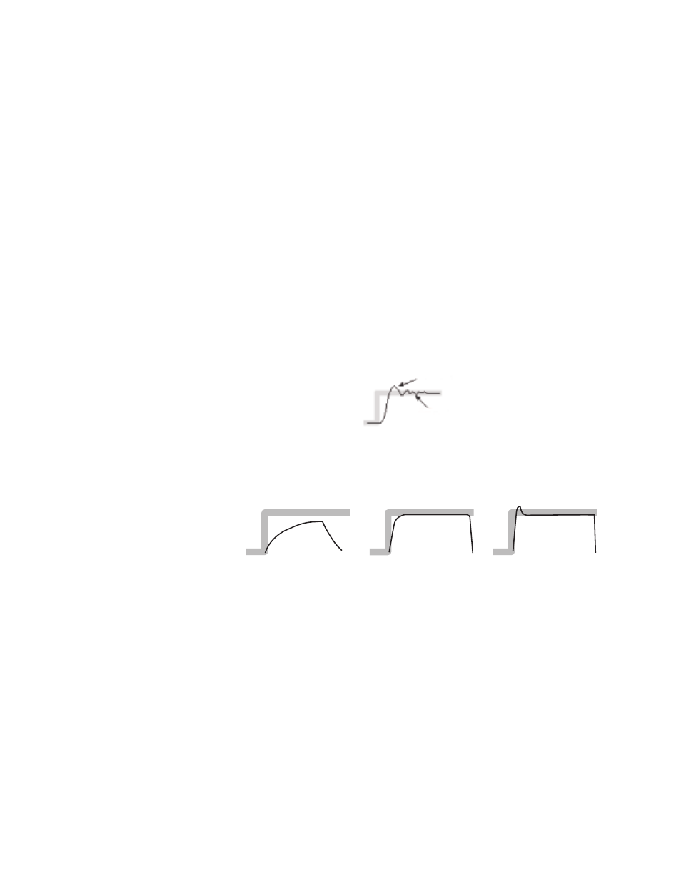
For optimal system response, tune the inner loop to be relatively less
responsive and more stable than a typical outer loop.
A. For Rate Input Selection, select Spool Position.
B. Increase Inner Loop Gain until you see a little overshoot on the
oscilloscope.
C. Slightly increase the Inner Loop Rate to eliminate this overshoot.
When properly tuned, the waveform should be a square wave with
rounded corners, having no overshoot.
Zero the Spool Position Signal
This task matches the electronic null of the spool position signal with the
mechanical null position of the servovalve pilot spool.
During inner loop tuning, it may be necessary to complete this procedure if the
spool position signal voltage is not approximately equal (though opposite
polarity) at opposite endcaps of a servovalve.
Ringing
Overshoot
Too Low
Correct
Too High