Sensor calibration, Sensor calibration 45 – MTS Series 793 User Manual
Page 45
About Calibration
MTS Series 793 Tuning and Calibration
Introduction
45
Sensor Calibration
Sensors convert a measured mechanical value (such as force, displacement, or
pressure) into a corresponding electrical signal. Each sensor requires
conditioning (such as AC or DC excitation) in order to output a feedback signal
that can be used by your servo controller.
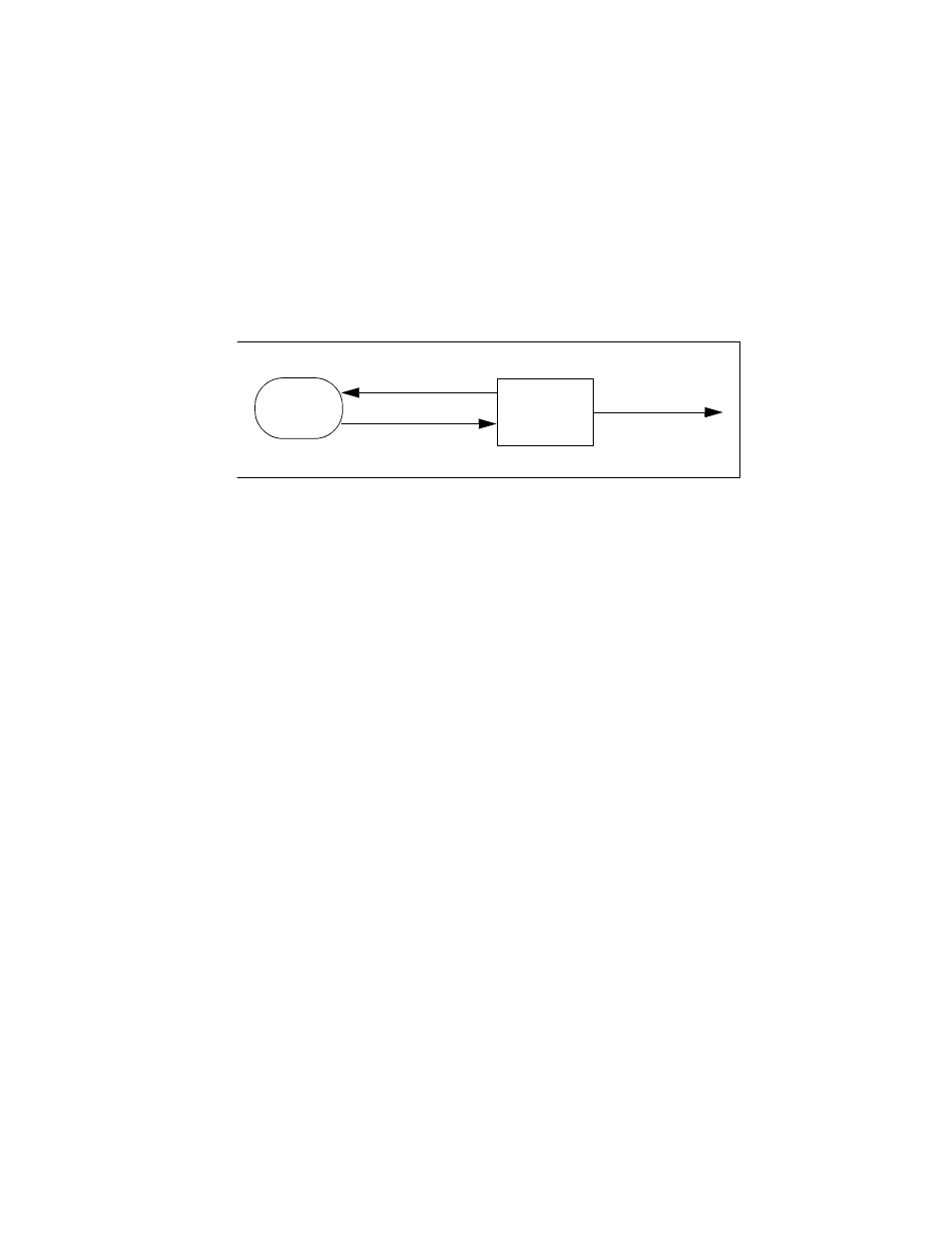
Sensor/Conditioner Signal Diagram
Sensor output
Each sensor/conditioner pair must be calibrated to output a voltage that is
proportional to the measured output (which may be displacement, force, or some
other dimension).
For example, a 10-cm LVDT/AC conditioner pair (connected to a 10-cm
actuator) is typically calibrated to output:
•
0 volts at the piston midstroke position (0 cm)
•
+10 volts at maximum piston retraction (–5 cm)
•
–10 volts at maximum piston extension (+5 cm)
Sensor calibration
data base
The calibration procedure creates a calibration data base for each range of a
sensor. The data base that is created includes:
•
Calibration data points
•
Sensor information (model, type, serial number, calibration date)
•
Equipment information (identifies the equipment used in the calibration)
•
Conditioner information (serial number, model number, excitation voltage,
circuit parameters)
Force Sensor
Calibration
Calibrating a force sensor requires a load standard. A load standard can be a
special calibrated force sensor with its own electronics or a set of calibrated dead
weights.
Sensor
Conditioner
Module
Excitation
Signal
Sensor
Signal
Feedback
Signal