MTS Series 793 User Manual
Page 188
MTS Series 793 Tuning and Calibration
Force Sensor Calibration
Calibration Procedures
188
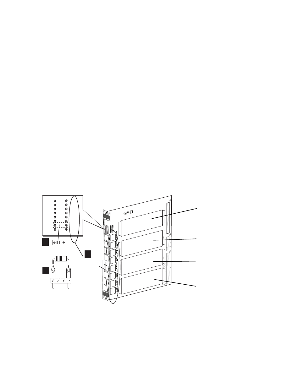
How to Install a Shunt-Calibration Resistor on an I/O Carrier Board
The Model 494.40 I/O Carrier board has a front-panel socket where you can
insert shunt-calibration plug assembly for use with DUC cards. Each socket is
associated with one of the eight RJ-50 connectors on the front panel.
1. Determine the RJ-50 connector(s) used by the transducer(s).
Note
Each mezzanine-card slot on the I/O carrier board connects to two RJ-50
connectors on the front of the I/O carrier board.
2. Solder the shunt-calibration resistors to an MTS shunt-calibration plug
assembly (MTS 11-433-826).
Note
The shunt-calibration plug assembly includes plug assemblies for eight
shunt resistors. Each resistor should be labeled with its resistance value
and transducer serial number.
3. Insert the shunt-calibration plug assemblies into the front-panel sockets.
Note
If you use MTS TEDS modules or MTS transducers with integrated
shunt-calibration resistors, you must insert a jumper plug (MTS 100-188-
097) into the socket for each transducer input where you will use the
integrated shunt-calibration resistor.
1
2
3
4
5
6
7
8
J1A
J1B
J2A
J2B
J3A
J3B
J4A
J4B
Connector
Numbering
Shunt-Calibration
Plug Assembly
2
1
3
1
2
3
4
5
6
7
8
J1A
J1B
J2A
J2B
J3A
J3B
J4A
J4B
Card Slot 1
uses RJ-50 connectors
J1A and J1B
Card Slot 2
uses RJ-50 connectors
J2A and J2B
Card Slot 3
uses RJ-50 connectors
J3A and J3B
Card Slot 4
uses RJ-50 connectors
J4A and J4B