2 parallel interface – Dascom 7010 Programmers Manual DMX User Manual
Page 138
1-136
5.2 Parallel Interface
1 Specifications
Transmission system: 8 bits parallel (compatibility mode)
Synchronization:
Strobe pulse
Handshake:
ACKNLG and BUSY
Signal logic level:
TTL
2 Usable interface connector
Printer side:
36-pin amphenol type
A standard parallel interface should be used. (The shortest distance should
be used for the interface cable.)
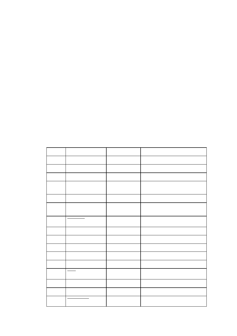
3 Connector signal arrangement
Pin No.
Signal name
Input/Output
Function
1
STROBE
Input
Strobe signal to read 8-bit data
2-9
DATA1-8
Input
8-bit parallel signal
10
ACKNLG
Output
8-bit data request signal
11
BUSY
Output
Signal to indicate printer BUSY
status
12
PERROR
Output
Signal to indicate paper out
13
SELECT
Output
Signal to indicate whether
printer is on-line or off-line
14
AUTOFD
Input
Not used
15
NC
-
Not used
16
GND
-
Ground
17
FGND
-
Frame ground
18
P.L.H.
Output
Not used
19-30
GND
-
Ground
31
INIT
Input
Invalid (ignored)
32
FAULT
Output
Signal to indicate printer error
33-35
NC
-
Not used
36
SELECTIN
Input
Note used