8 cab heater/air conditioning controls, Cab heater/air conditioning controls – JLG 4017PS Service Manual User Manual
Page 92
Cab and Covers
4-8
3706PS, 3707PS, 4014PS, 4017PS, 33.7, 37.6, 37.7
3. Connect the previously labeled electrical connectors
to the heater assembly.
4. Replace the heater assembly filter if needed, refer to
Section 4.3.7, c. “Heater Assembly Filter
Replacement.”
5. Fill the cooling system completely with coolant,
allowing time for the coolant to fill the engine block.
The cooling system capacity is listed in Section 2.5,
“Fluids, Lubricants and Capacities.”
6. Properly connect the battery.
7. Start the engine, run it briefly at low idle and check
the machine for any visual sign of fluid leakage.
Note: STOP the engine immediately if any leakage is
noted, and make any necessary repairs before
continuing.
8. Wait for the engine to cool and check the coolant
level. Add coolant as required to bring the coolant to
the proper level.
9. Install the protective cover to the heater assembly.
10. Install the intake box to the heater box.
11. Install the small cab floor plate.
12. Install the plastic side cover in the cab.
13. Install the cab floor mat.
14. Close and secure the engine cover.
15. Remove the Do Not Operate Tag from the ignition
key switch and the steering wheel.
c. Heater Assembly Filter Replacement
1. Remove the cab floor mat.
2. Remove the small cab floor plate (4).
3. Remove the four bolts securing the intake box (5) to
the heater box.
4. Remove the heater assembly filter (10) and replace
with a new filter.
5. Install the intake box to the heater box.
6. Install the small cab floor plate.
7. Install the cab floor mat.
4.3.8
Cab Heater/Air Conditioning Controls
a. Cab Heater Controls Removal
1. Park the machine on a firm, level surface, level the
machine, fully retract the boom, lower the boom,
place the transmission control lever in
(N) NEUTRAL, engage the park brake and shut the
engine OFF.
2. Place a Do Not Operate Tag on both the ignition key
switch and the steering wheel.
3. Open the engine cover. Allow the system fluids to
cool.
4. Properly disconnect the battery.
5. Remove the plastic side cover in the cab to gain
access to the control cables and electronics. If
necessary, remove the seat for more accessibility.
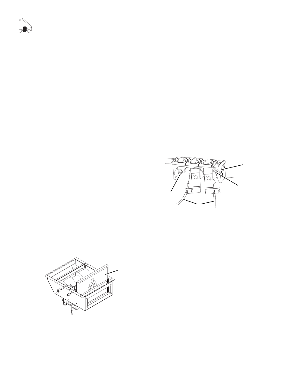
6. Label and disconnect the control cables (11)
attached to the control knob mechanisms.
7. Label and disconnect the electrical connectors (12)
attached to the control box.
8. Depress the side clips (13) and push the control box
through the dash panel.
b. Disassembly
DO NOT disassemble the cab heater and fan controls.
The controls are not serviceable. Replace controls if
found to be defective.
c. Installation and Testing
1. Install the control box into the dash panel until the
side clips firmly hold the box.
2. Connect the previously labeled electrical connectors
to the appropriate locations.
3. Connect the previously labeled control cables to the
appropriate control knob mechanisms.
4. Verify the water valve on the bottom of the heater
assembly opens completely.
MAM0930
10
MAM0310
11
13
12
12