5 joystick assembly, Joystick assembly – JLG 4017PS Service Manual User Manual
Page 90
Cab and Covers
4-6
3706PS, 3707PS, 4014PS, 4017PS, 33.7, 37.6, 37.7
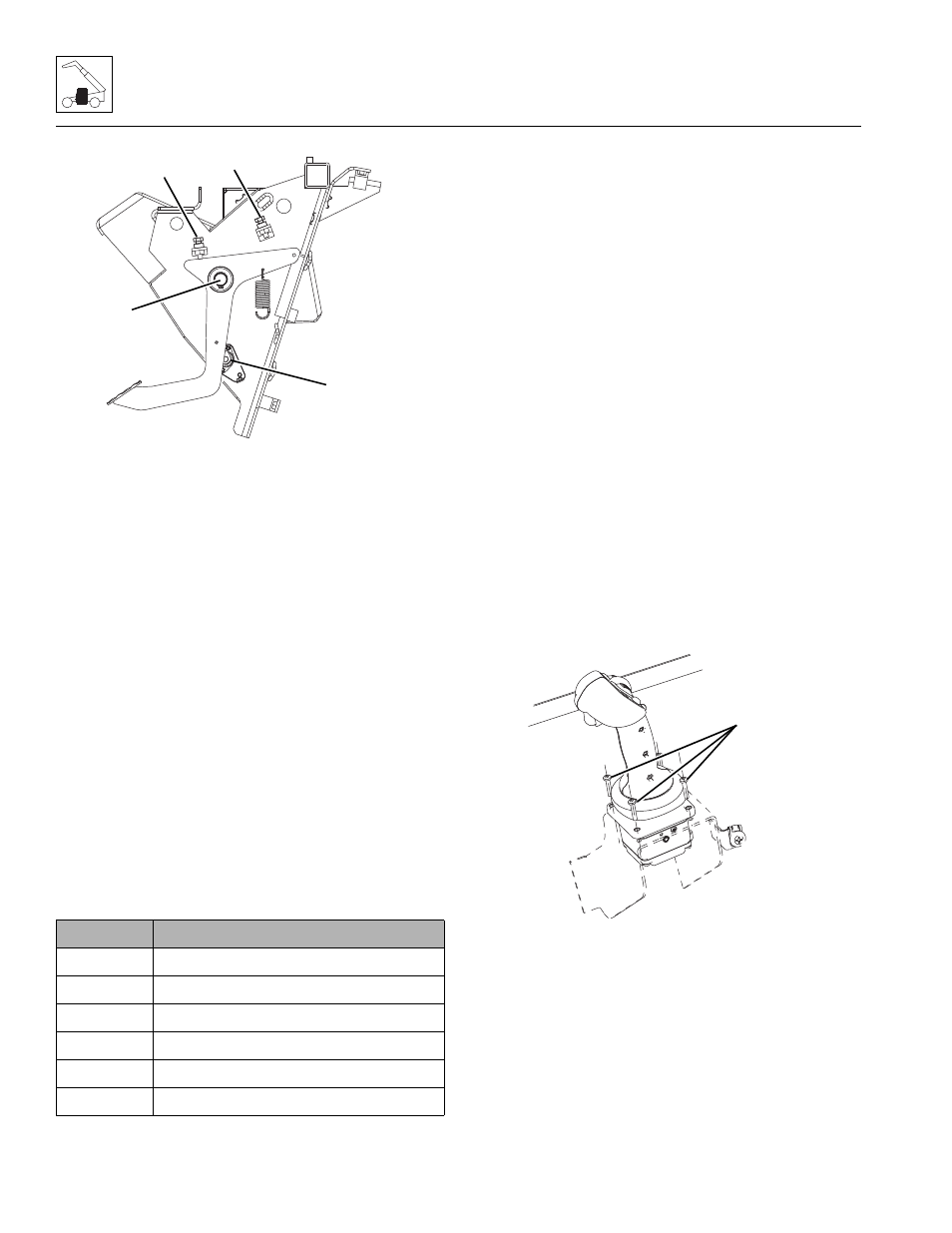
5. Disconnect the sensor linkage from the pedal (1).
6. Remove the snap ring (2) securing the throttle pedal
to the mounting post.
7. Remove the throttle pedal assembly from the cab.
b. Throttle Pedal Installation
1. Position the throttle pedal in its mounting location
within the cab.
2. Secure the throttle pedal into position with the
previously used snap ring.
3. Install the pedal tension spring.
4. Install the sensor linkage to the pedal.
5. Properly connect the battery.
6. Close and secure the engine cover.
7. Remove the Do Not Operate Tag from the ignition
key switch and the steering wheel.
c. Throttle Pedal Adjustment
The throttle pedal provides analog position feedback
(APS OUT), and switches to confirm idle pedal position.
1. Loosen the lock nuts on each stop bolts (3 & 4).
2. Connect multimeter to wires connected to pins “B”
and “C” on the wire harness connection at the
throttle pedal.
3. Turn ignition to the ON position.
4. Adjust closed throttle stop adjustment bolt (3) to
0.65V - 0.85V.
5. Depress the throttle pedal and adjust open throttle
stop adjustment bolt (4) to 3.65V - 3.85V.
6. Tighten lock nuts on each stop bolts (3 & 4).
7. Verify the above readings are correct and adjust if
necessary.
4.3.5
Joystick Assembly
a. Joystick Assembly Removal
1. Park the machine on a firm, level surface, level the
machine, fully retract the boom, lower the boom,
place the travel select lever in the (N) NEUTRAL
position, engage the parking brake and turn the
engine OFF.
2. Place a Do Not Operate Tag on both the ignition key
switch and the steering wheel.
3. Properly disconnect the battery.
4. Remove the bolts securing the boom joystick to the
cab (5).
5. Lift the joystick from its mounting position.
6. Label and disconnect the electrical connectors
attached to the joystick.
7. Remove the joystick assembly.
Pin
Functionality
A
APS OUT
B
Ground
C
VCC
D
IVS1
E
IVS2
F
Reserved (do not connect)
MAM0230
2
1
3
4
MAM0370
5