2 boom system - two section, 1 boom system operation, 3 boom assembly maintenance – JLG 4017PS Service Manual User Manual
Page 42: 1 complete boom removal, Boom system - two section, Boom assembly maintenance, Boom system operation, Complete boom removal, Warning
Boom
3-4
3706PS, 3707PS, 4014PS, 4017PS, 33.7, 37.6, 37.7
3.2
BOOM SYSTEM - TWO SECTION
3.2.1
Boom System Operation
The boom operates via an interchange among the
electrical, hydraulic and mechanical systems. Components
involved include the joystick, tilt cylinder, extend/retract
cylinder, lift/lower cylinder, compensating cylinder,
various pivots, supporting hardware and other components.
3.3
BOOM ASSEMBLY MAINTENANCE
The boom assembly consists of the first and second
section booms and supporting hardware.
Note: Before removing the boom or boom section, the
carriage or any other attachment must be removed from
the quick coupler.
Before beginning, conduct a visual inspection of the
machine and work area, and review the task about to be
undertaken. Read, understand and follow these
instructions.
During service of the boom, perform the following:
1. Check wear pads. (Refer to Section 3.17.1, “Wear
2. Apply grease at all lubrication points (grease fittings).
Refer to Section 2.7, “Lubrication Schedule.”
3. Check for proper operation by operating all boom
functions through their full ranges of motion several
times.
Depending on your particular circumstance, the following
procedures explain the removal/installation of individual
boom sections or removal/installation of the complete
boom.
3.3.1
Complete Boom Removal
While the boom sections can be separated from each
other on the machine, it is much safer, more efficient and
more cost- effective to remove the complete boom
assembly from the machine and place it on suitable
supports for separation. Work can then progress at a
normal working height.
Note: When removing a complete boom assembly use
a hoist or crane with a minimum lift capacity of 6000 lbs.
1. Remove any attachment from the quick coupler
assembly. Refer to the Operation & Safety Manual.
2. Park the machine on a hard, level surface, fully
retract the boom, Raise the boom to allow access to
the lift/lower cylinder and the compensation cylinder
pivot pins, place the transmission control lever in
(N) NEUTRAL, engage the park brake and shut the
engine OFF.
3. Place a Do Not Operate Tag on both the ignition key
switch and the steering wheel.
4. Properly disconnect the battery.
5. Open the engine cover. Allow the system fluids to
cool.
6. Remove the quick coupler assembly. Refer to
Section 3.18.1, “Quick Coupler Removal (3706PS,
3707PS, 33.7, 37.6 & 37.7).”
7. Remove boom angle sensor arm. Refer to Section
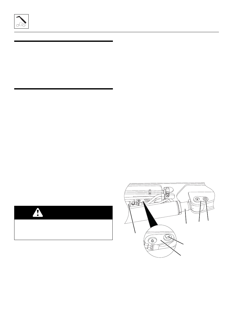
8. Support the boom by placing a sling around the
boom head. Support the lift/lower cylinder (1) and
remove the lock bolt (2) and then the rod end pin (3).
Lower the lift/lower cylinder onto the frame rails.
WARNING
NEVER weld or drill the boom unless approved in
writing by JLG. The structural integrity of the boom
will be impaired if subjected to any repair involving
welding or drilling.
MAM0640
2
3
1
4
5
6