2 cylinder pressure checking, 3 steering cylinders, Cylinder pressure checking – JLG 4017PS Service Manual User Manual
Page 154: Steering cylinders
Hydraulic System
8-22
3706PS, 3707PS, 4014PS, 4017PS, 33.7, 37.6, 37.7
7. Screw the head gland into the cylinder barrel and
tighten with a spanner wrench. Refer to Section
8.11.4, “Cylinder Torque Specifications” for torque
specifications for the head gland.
8. If applicable, install new counter balance valve into
block on the cylinder barrel.
e. General Cylinder Installation
1. Grease the bushings at the ends of the hydraulic
cylinder. Using an appropriate sling, lift the cylinder
into it’s mounting position.
2. Align cylinder bushing and install pin, lock bolt or
retaining clip.
3. Connect the hydraulic hoses in relation to the labels
or markings made during removal.
4. Before starting the machine, check fluid level of the
hydraulic fluid reservoir and if necessary fill to full
mark with oil.
5. Start the machine and run at low idle for about one
minute. Slowly activate hydraulic cylinder function in
both directions allowing cylinder to fill with hydraulic
oil.
6. Inspect for leaks and check level of hydraulic fluid in
reservoir. Add hydraulic fluid if needed. Shut the
engine OFF.
7. Wipe up any hydraulic fluid spillage in, on, near and
around the machine, work area and tools.
8. Close and secure the engine cover.
8.11.2
Cylinder Pressure Checking
Attach a 345 bar (5000 psi) gauge to the test port on the
P1 port on the hydraulic manifold to check the system
pressure. For more information, refer to Section 8.4.1,
“Pressure Checks and Adjustments.”
Note: If a hydraulic cylinder pressure is greater than the
main control valve pressure, increase the main control
valve pressure by adjusting the main relief. Generally,
one half turn clockwise will be adequate to check an
individual circuit. Activate the circuit and if pressure is
obtained turn the main relief counter clockwise one half
turn. Re-check the main relief setting and adjust if
necessary.
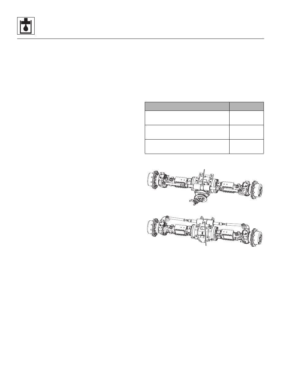
8.11.3
Steering Cylinders
The steer cylinder is attached to each axle center
housing. The steer cylinder is covered in the appropriate
manufacturer’s axle literature.Detailed axle service
instructions (covering the axle, differential, brakes and
wheel-end safety, repair, disassembly, reassembly,
adjustment and troubleshooting information) are
provided in the appropriate Axle Disassembly &
Assembly Manual.
Machine
Manual P/N
3706PS, 3707PS, 4014PS 33.7, 37.6
&
37.7 (Mechanical Park Brake)
31211060
4017PS
(Mechanical Park Brake)
31211062
4014PS & 4017PS
(Hydraulic Park Brake)
31211058
MAM2710
REAR AXLE STEER CYLINDER
FRONT AXLE STEER CYLINDER