4 electronic throttle pedal, Electronic throttle pedal – JLG 4017PS Service Manual User Manual
Page 89
4-5
3706PS, 3707PS, 4014PS, 4017PS, 33.7, 37.6, 37.7
Cab and Covers
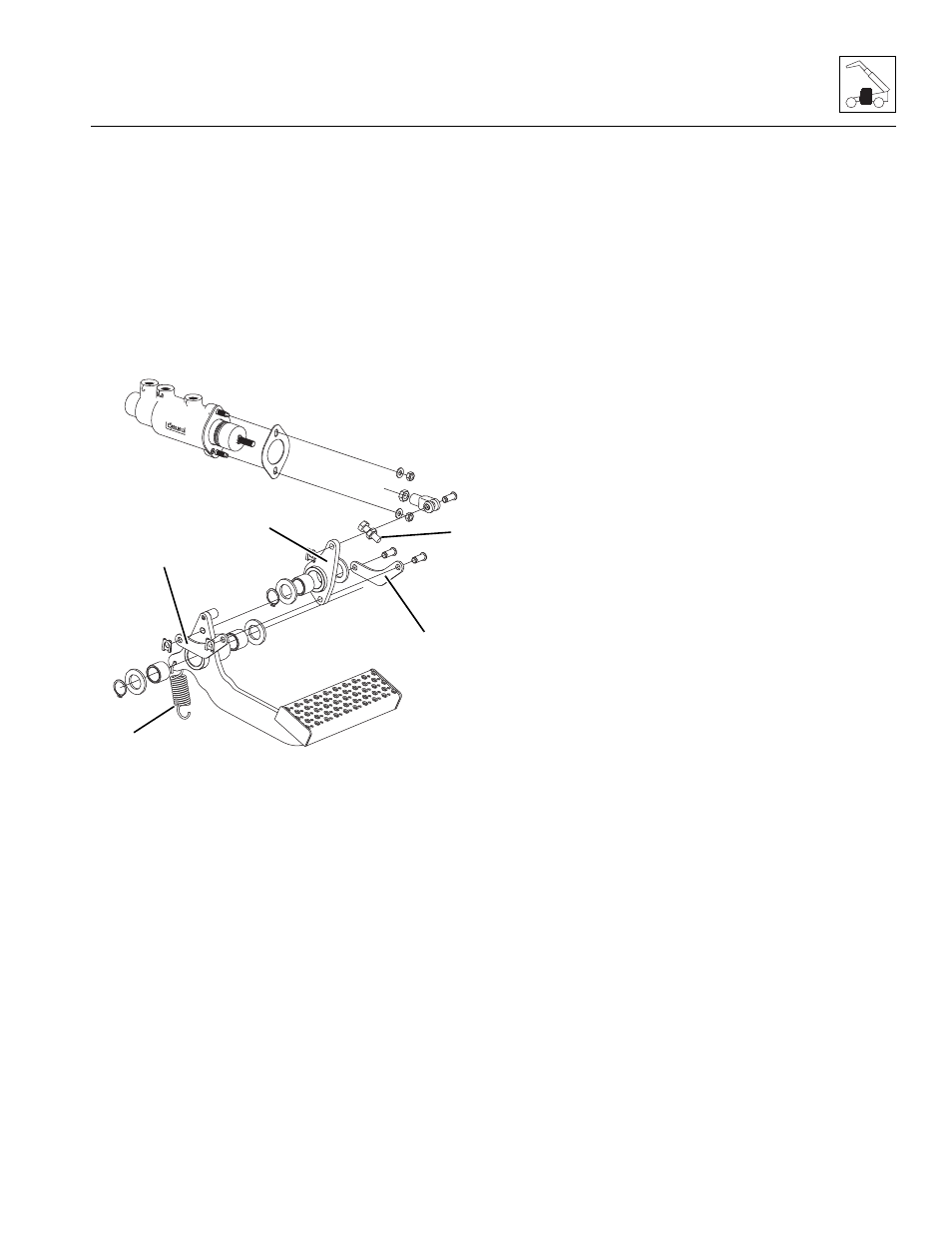
c. Service Brake Pedal Removal
1. Park the machine on a firm, level surface, level the
machine, fully retract the boom, lower the boom,
place the travel select lever in the (N) NEUTRAL
position, engage the parking brake and turn the
engine OFF.
2. Place a Do Not Operate Tag on both the ignition key
switch and the steering wheel.
3. Open the engine cover. Allow the system fluids to
cool.
4. Properly disconnect the battery.
5. Remove the tension spring (7) from the brake pedal.
6. Remove the clips securing the brake pedal and
linkage to the service brake valve.
7. Remove the connecting plates (8) between the
pedal and the lever assembly (9).
8. Remove the two snap rings.
9. Remove the pedal and lever assembly keeping note
of location of all washers, bushings, etc.
d. Service Brake Pedal Installation
1. Install the brake pedal and lever assembly (9) onto
their mounting posts with the previously used
washers, bushings etc.
2. Install the two snap rings.
3. Install the connecting plates (8) between the pedal
and the lever assembly with the previously used
clips.
4. Install the pedal tension spring (7).
5. Be sure the brake pedal has the correct range of motion.
If the pedal requires adjustment, refer to Section
4.3.3, e. “Service Brake Pedal Adjustment.”
6. Properly connect the battery.
7. Close and secure the engine cover.
8. Remove the Do Not Operate Tag from the ignition
key switch and the steering wheel.
e. Service Brake Pedal Adjustment
1. Loosen the pedal adjustment bolt. The adjustment
bolt cannot contact the linkage during adjustment.
2. Remove the master cylinder dust cover to gain
access to the master cylinder plunger.
3. Rotate the master cylinder push rod clockwise until
the push rod bottoms in the plunger. Rotate the push
rod a quarter turn counterclockwise and tighten the
adjustment bolt locknut. There should be
0,6-1,2 mm (0.2-0.8 in) of axial play between the
push rod and plunger.
4. Screw in the adjustment bolt (10) by hand until the
bolt makes contact with the linkage. Turn the bolt an
additional one turn and secure with the locknut.
5. Verify that the pedal height is no less than
134 mm (5.3 in) from cab floor (mat included).
6. Verify that the master cylinder plunger is flush with
master cylinder body.
7. Install the master cylinder dust cover.
4.3.4
Electronic Throttle Pedal
a. Throttle Pedal Removal
1. Park the machine on a firm, level surface, level the
machine, fully retract the boom, lower the boom,
place the travel select lever in the (N) NEUTRAL
position, engage the parking brake and turn the
engine OFF.
2. Place a Do Not Operate Tag on both the ignition key
switch and the steering wheel.
3. Properly disconnect the battery.
4. Remove the tension spring from the pedal.
MAM0220
7
8
9
8
10