8 second boom section installation, Second boom section installation, Warning – JLG 4017PS Service Manual User Manual
Page 47
3-9
3706PS, 3707PS, 4014PS, 4017PS, 33.7, 37.6, 37.7
Boom
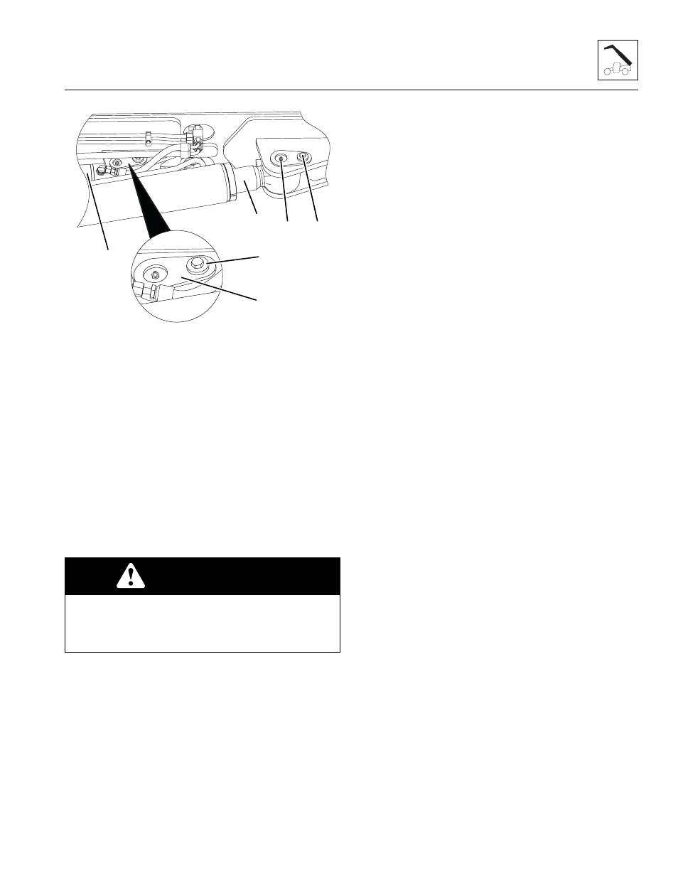
5. With a sling in place, raise the compensation
cylinder (5) into place and install the pin (6) and lock
bolt (7) to the barrel end of the compensating
cylinder on the first boom section.
6. With the sling still in place, install the rod end of the
lift/lower cylinder (8), pin (9) and lock bolt (10). Apply
Loctite
®
242
TM
and torque to 90 Nm (66 lb-ft).
Note: Raising the boom up or down with the sling may
be necessary so the boom, compensating and lift/lower
cylinder bores can be aligned for easier pin installation.
7. Remove sling.
8. Temporarily connect the battery.
9. Start the machine and lower the first boom section to
a level position.
10. Properly disconnect the battery.
3.3.8
Second Boom Section Installation
Note: Light lubrication of the boom wear surfaces with a
factory authorized grease is recommended to keep the
boom wear surfaces lubricated properly. Lubrication of
the boom wear surfaces is also recommended when the
machine is stored, to help prevent rusting.
1. If previously removed, install the extend/retract
cylinder into the rear of the second boom section.
Refer to Section 3.3.6, 3.3.6. “Extend/Retract
Cylinder Installation.”
2. Using suitable slings, balance the second boom
section, lift and carefully guide the boom into place.
3. Install the wear pads, shims and bolts to their proper
location at the front inside of the first boom section.
DO NOT tighten the wear pads at this time.
4. Feed the tilt cylinder hoses and if equipped, the
auxiliary hoses through the channel above the
extend/retract cylinder.
5. Install the wear pads, shims and bolts previously
removed from the rear of the second boom section.
DO NOT tighten the wear pads at this time.
6. Uncap and connect the previously labeled extend/
retract cylinder hoses to the extend/retract cylinder.
Refer to Section 2.3.3, “Hydraulic Hose Torque
Chart,” for proper hose torque.
7. Uncap and connect the previously labeled tilt hoses
and (if equipped) auxiliary hoses to the appropriate
cylinder. Refer to Section 2.3.3, “Hydraulic Hose
Torque Chart,” for proper hose torque.
8. Install the boom angle sensor arm. Refer to Section
9. Adjust and shim each wear pad as needed. Refer to
Section 3.17, “Boom Wear Pads.”
10. Properly connect the battery.
11. Start the engine and operate all boom functions
several times to bleed any air out of the hydraulic
system. Check for fluid leaks. Check the hydraulic
fluid level in the tank and add fluid as required.
12. Clean up all debris, hydraulic fluid, etc., in, on, near
and around the machine.
13. Close and secure the engine cover.
14. Remove the Do Not Operate Tag from the ignition
key switch and the steering wheel.
WARNING
DO NOT activate ANY boom function other than the
boom lift/lower function. Activating the extend/retract,
tilt or auxiliary function could cause hydraulic oil to
spray onto the machine and/or surrounding areas.
MAM0640
7
6
5
8
9
10