2 reversing fan valve, Reversing fan valve – JLG 4017PS Service Manual User Manual
Page 148
Hydraulic System
8-16
3706PS, 3707PS, 4014PS, 4017PS, 33.7, 37.6, 37.7
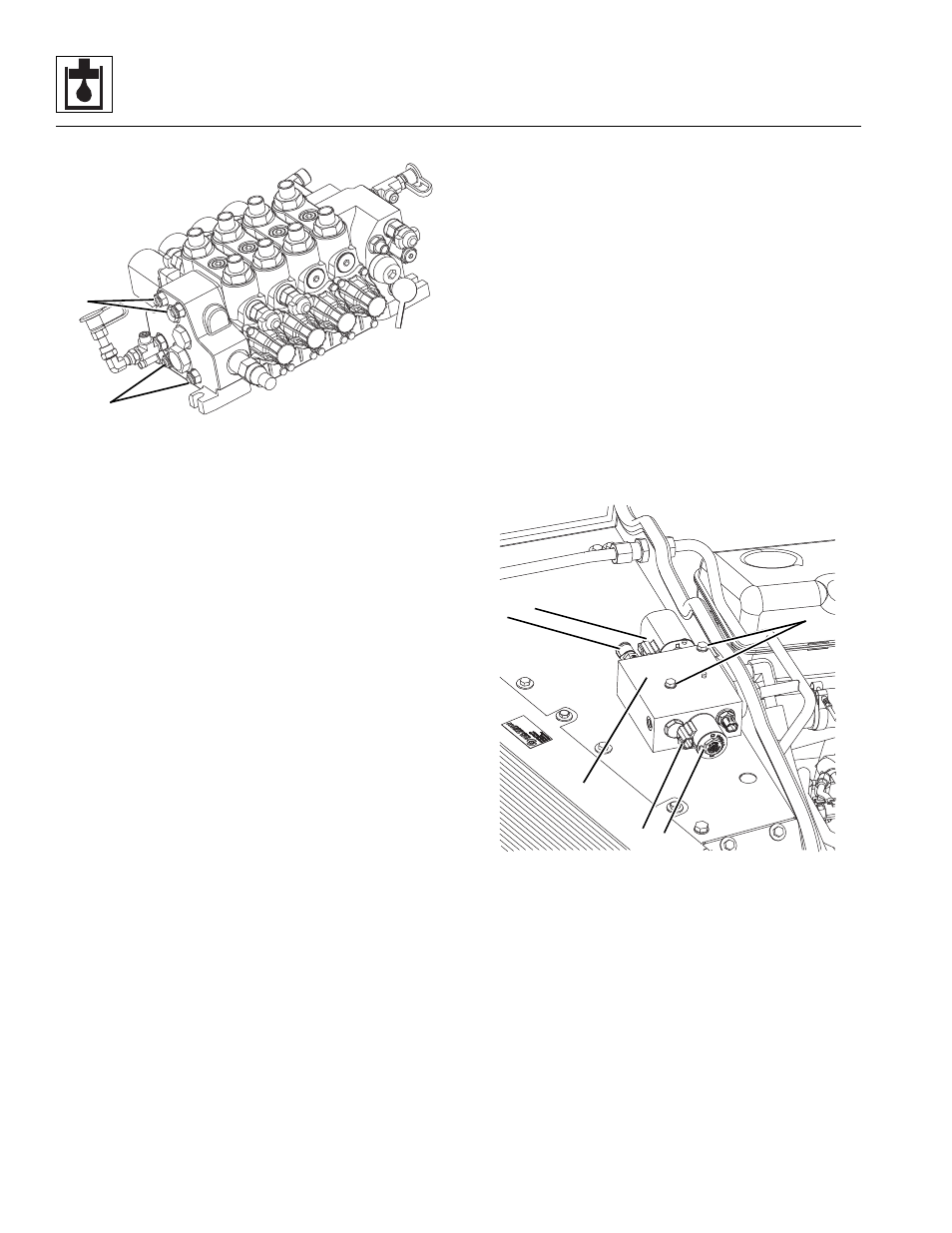
5. Install the nuts on the tie rods (5) and torque to
25Nm (18.5 lb-ft).
f.
Main Control Valve Installation
1. Install the main control valve onto the frame, aligning
the bolts with the holes in the end sections of the
main control valve. Slide the main control valve into
position, and tighten the bolts.
2. Prime the main control valve by filling the inlet
openings with fresh, filtered hydraulic oil from a
clean container, before attaching the hoses.
3. Use new oiled o-rings as required. Uncap and
connect all hoses, clamps, etc. to the main control
valve.
4. Check the routing of all hoses, wiring and tubing for
sharp bends or interference with any rotating
members, and install tie wraps and/or protective
conduit as required. Tighten all tube and hose
clamps.
5. Fill the hydraulic oil reservoir. Refer to Section 8.7.2,
“Hydraulic Oil Reservoir Filling.”
6. Properly connect the battery.
7. Start the engine and run at approximately one-third
to one-half throttle for about one minute without
moving the machine or operating any hydraulic
functions.
8. Inspect for leaks and check the level of the hydraulic
fluid in the reservoir. Shut the engine OFF.
9. Wipe up any hydraulic fluid spillage in, on, near and
around the machine, work area and tools.
10. Close and secure the engine cover.
11. Remove the Do Not Operate Tag from the ignition
key switch and the steering wheel.
g. Main Control Valve Test
Conduct a pressure check of the hydraulic system in its
entirety. Adjust pressure(s) as required. Refer to Section
8.5.1, “Hydraulic Pressures.”
8.10.2
Reversing Fan Valve
a. Reversing Fan Removal
1. Park the machine on a firm, level surface, level the
machine, fully retract the boom, lower the boom,
place the transmission control lever in (N) NEUTRAL,
engage the park brake and shut the engine OFF.
2. Place a Do Not Operate Tag on both the ignition key
switch and the steering wheel.
3. Open the engine cover. Allow the system fluids to
cool.
4. Properly disconnect the battery.
5. Label and disconnect the electrical connectors (7)
on each end of the reversing fan valve (6).
6. Thoroughly clean the reversing fan valve and
surrounding area, including all hoses and fittings,
before proceeding.
7. Place a suitable container to catch hydraulic fluid
drainage beneath the reversing fan valve.
8. Label, disconnect and cap the four hydraulic hoses
attached to the back and bottom of the reversing fan
valve.
9. Loosen and remove the two mounting bolts,
washers and nuts (8) from the reversing fan valve.
MZ6400
5
5
MZ6850
6
7
7
8
10
9