JLG 4017PS Service Manual User Manual
Page 196
Electrical System
9-38
3706PS, 3707PS, 4014PS, 4017PS, 33.7, 37.6, 37.7
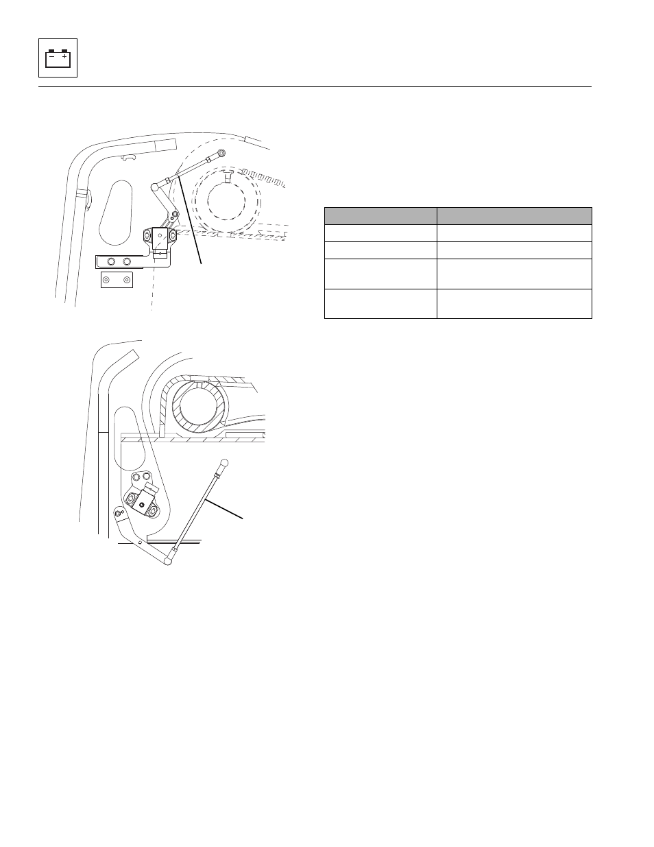
5. Disconnect the boom angle sensor electrical
connector.
6. Loosen and remove the nut holding the rod
assembly (3) to the sensor arm.
7. Loosen and remove the two bolts holding the sensor
to the sensor bracket.
8. Remove the sensor assembly.
9. If necessary, remove the sensor bracket.
b. Boom Angle Sensor Inspection and Replacement
Inspect the sensor and the wiring harness connector
terminals for continuity. Replace a defective or faulty
sensor with a new sensor.
c. Boom Angle Sensor Installation
1. If necessary, install the sensor bracket.
2. Install the sensor assembly to the sensor seat and
tighten both bolts.
3. Install the rod end to the sensor arm and tighten nut.
4. If necessary, measure and set the rod length (3) as
required.
5. Plug the electrical connector into the sensor
assembly.
6. Properly connect the battery.
7. Close and secure the engine cover.
8. Remove the Do Not Operate Tag from the ignition
key switch and the steering wheel.
d. Boom Angle Sensor Adjustment
1. Access Level 2 can be reached by pressing buttons
C and OK at the same time.
2. Enter Access Level 2 password 33271.
3. Choose Calibration menu and select “Boom Angle”.
4. Press OK button when asked “Calibrate Boom Angle
Sensor?”.
5. Follow prompts. First move boom to lowest position,
press OK button.
6. Follow prompts. Move boom to highest position,
press OK button.
7. If calibration is successful, Analyzer will indicate
“Calibration: Complete”.
If calibration fails, Analyzer will indicate “Calibration
Failed”. The boom angle sensor position may need
to be adjusted or the boom sensor rod may need
adjusted.
MAM0400
3
3706PS, 3707PS, 33.7, 37.6 & 37.7
MAM0610
3
4014PS & 4017PS
Machine
Rod Length
3706PS, 33.7 & 37.6
143.1 ±1mm (5.63 ± 0.0.04 in)
3707PS, 37.7
142.7 ±1mm (5.61 ± 0.0.04 in)
4014PS Platform &
4017PS
220.0 ±1mm (8.7 ± 0.0.04 in)
4014PS Platform &
4017PS Platform
215.0 ±1mm (8.5 ± 0.0.04 in)