2 axle installation, Axle installation – JLG 4017PS Service Manual User Manual
Page 100
Axles, Drive Shafts, Wheels and Tires
5-4
3706PS, 3707PS, 4014PS, 4017PS, 33.7, 37.6, 37.7
6. If the axle will be disassembled after removal, place
a suitable receptacle under the axle (1) and wheel
hubs (3) drain plugs. Remove the drain plugs and
allow the oil to drain into the receptacle. Transfer the
used oil into a suitable covered container, and label
the container as “Used Oil.” Dispose of the used oil
at an approved recycling facility.
7. Label, disconnect and cap the steering and brake
lines at the axle. Wipe up any spilled oil.
8. Block the front and rear of both tires on the axle that
is not being removed. Ensure that the machine will
remain in place during axle removal before
proceeding.
9. Raise the machine using a suitable jack or hoist.
Place suitable supports under both sides of the
frame and lower the machine onto the supports.
Ensure that the machine will remain in place during
axle removal.
10. Support the axle that is being removed with a suitable
jack, hoist or overhead crane and sling. DO NOT
raise the axle or the machine.
11. Remove both wheel and tire assemblies from the
axle that is being removed. Refer to Section 5.11.1,
“Removing Wheel and Tire Assembly from
Machine.”
Note: The wheel and tire assemblies must be re-installed
later with the directional tread pattern “arrows” facing in
the direction of forward travel.
12. Remove the drive shaft assembly. Refer to Section
5.10.3, “Drive Shaft Removal.”
13. 4014PS & 4017PS Only: On the front axle, remove
the lower position cylinder mount pin for the front
cylinder. Tap the cylinder mount pin out, and move
the cylinder to prevent it from interfering with axle
removal. If a new axle will be installed, remove the
frame level mounting plate from the axle.
14. Remove the bolts and locknuts securing the axle to
the frame.
15. Remove the axles from the machine using the jack,
hoist or overhead crane and sling supporting the
axle. DO NOT raise or otherwise disturb the
machine while removing the axle. Balance the axle
and prevent it from tipping, turning or falling while
removing it from beneath the machine. Place the
axle on a suitable support or holding stand.
5.4.2
Axle Installation
1. Before proceeding, ensure that the machine will
remain in place during axle installation. Block the
front and rear of both tires on the axle that is already
installed on the machine.
2. If applicable, raise the machine using a suitable jack
or hoist. Place suitable supports beneath the frame
and lower the machine onto the supports, allowing
enough room for axle installation. Ensure that the
machine will remain in place during axle installation.
3. Using a suitable jack, hoist or overhead crane and
sling, remove the axle from its support or holding
stand. Balance the axle and prevent it from tipping,
turning or falling while positioning it beneath the
machine. DO NOT raise or otherwise disturb the
machine while installing the axle. Keep the axle
supported and balanced on the jack, hoist or
overhead crane and sling throughout the installation
procedure.
4. Position the axle under the frame, and align the axle
housings with the holes in the frame.
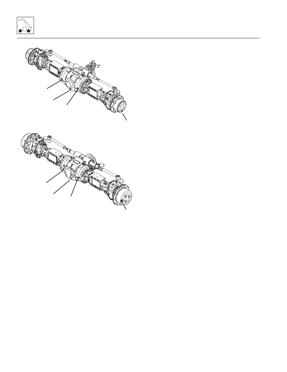
MZ2491
2
3706PS, 3707PS, 33.7, 36.7 & 37.7 FRONT
AXLE
3
1
2
MECHANICAL PARK BRAKE SHOWN
MZ2501
1
4014PS & 4017PS FRONT AXLE
3
2
2
MECHANICAL PARK BRAKE SHOWN