6 window wiper assembly, 7 heater/air conditioning system (if equipped), Window wiper assembly – JLG 4017PS Service Manual User Manual
Page 91: Heater/air conditioning system (if equipped), Caution
4-7
3706PS, 3707PS, 4014PS, 4017PS, 33.7, 37.6, 37.7
Cab and Covers
b. Joystick Assembly Installation
1. Connect the previously labeled electrical connectors
to the joystick.
2. Install the bolts securing the joystick to the cab.
3. Properly connect the battery.
4. Test the joystick functions.
5. Close and secure the engine cover.
6. Remove the Do Not Operate Tag from the ignition
key switch and the steering wheel.
4.3.6
Window Wiper Assembly
Refer to Section 9.11, “Window Wiper/Washer
Windshield Wiper Motor,” for removal and installation
information.
4.3.7
Heater/Air Conditioning System
(if Equipped)
a. Heater Assembly Removal
1. Park the machine on a firm, level surface, level the
machine, fully retract the boom, lower the boom,
place the travel select lever in the (N) NEUTRAL
position, engage the park brake and shut the engine
OFF.
2. Place a Do Not Operate Tag on both the ignition key
switch and the steering wheel.
3. Open the engine cover. Allow the system fluids to
cool.
4. Properly disconnect the battery.
5. Place a suitable container beneath the radiator.
Slowly turn the radiator cap to the first stop, and
allow any pressure to escape. Remove the radiator
cap.
6. Place a funnel at the base of the radiator to channel
the drained coolant into the container. Remove the
drain plug and allow the coolant to drain.
7. Transfer the coolant to a container with a cover, and
label as “Used Antifreeze.” Dispose of the used
coolant at an approved recycling facility.
8. Tighten the radiator drain plug.
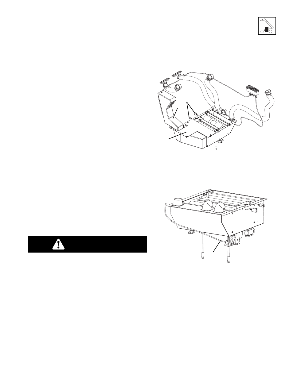
9. From under the cab, remove the protective cover to
the heater assembly.
10. Remove the cab floor mat.
11. Remove the small cab floor plate (6).
12. Remove the four bolts securing the intake box (7) to
the heater box.
13. Label and disconnect the electrical connections (8)
to the heater assembly.
14. Disconnect the cable (9) for the heater control knob
from the water valve.
15. Support the heater assembly from under the cab
16. Remove the bolts securing the heater assembly to
the cab. Remove the heater assembly.
b. Heater Assembly Installation
1. Position the heater assembly to its original orientation
under the cab. Secure with the previously used
hardware.
2. Connect the cable for the heater control knob to the
water valve.
CAUTION
The cooling system is under pressure. NEVER
remove the radiator cap while the cooling system is
hot. Wear safety glasses. Turn the radiator cap to the
first stop and allow pressure to escape before
removing the cap completely.
MAM0260
8
6
7
MAM0250
9