10 drive shafts, 1 drive shaft inspection, 2 drive shaft maintenance – JLG 4017PS Service Manual User Manual
Page 108: 3 drive shaft removal, 4 drive shaft cleaning and drying, 5 drive shaft installation, Drive shafts, Drive shaft inspection, Drive shaft maintenance, Drive shaft removal
Axles, Drive Shafts, Wheels and Tires
5-12
3706PS, 3707PS, 4014PS, 4017PS, 33.7, 37.6, 37.7
5.10
DRIVE SHAFTS
5.10.1
Drive Shaft Inspection
Inspect areas where the drive shaft flange yokes and slip
yokes mount to the drive shafts. Attempt to turn each
drive shaft in both directions. Look for excessive
looseness, missing parts, cracks or other damage. Worn
or damaged drive shafts and cross and bearing
assemblies may cause an excessive amount of vibration
or noise.
Note: To ensure optimum performance, the driveshaft
assemblies are specially balanced as a unit at the
factory. When servicing any flange yoke, slip yoke or
drive shaft tube, order a complete assembly if
components are bent or damaged. Refer to the
appropriate parts manual for ordering information.
Note: Any bolt removed from the drive shaft assembly
MUST be replaced. Do Not re-torque.
5.10.2
Drive Shaft Maintenance
Refer to Section 2.5, “Fluids, Lubricants and Capacities,”
for information regarding the lubrication of the grease
fittings on the drive shafts.
5.10.3
Drive Shaft Removal
1. Park the machine on a firm, level surface, level the
machine, fully retract the boom, lower the boom,
place the transmission control lever in (N) NEUTRAL,
engage the park brake and shut the engine OFF.
2. Place a Do Not Operate Tag on both the ignition key
switch and steering wheel.
3. Open the engine cover. Allow the system fluids to
cool.
4. Properly disconnect the battery.
5. Block the wheels.
6. The drive shaft assembly is a balanced assembly.
Mark the yoke and axle, transmission and the shaft
and slip yoke so that these components can be
returned to their original positions when reinstalled.
Yokes at both ends of the drive shaft must be in the
same plane to help prevent excessive vibration.
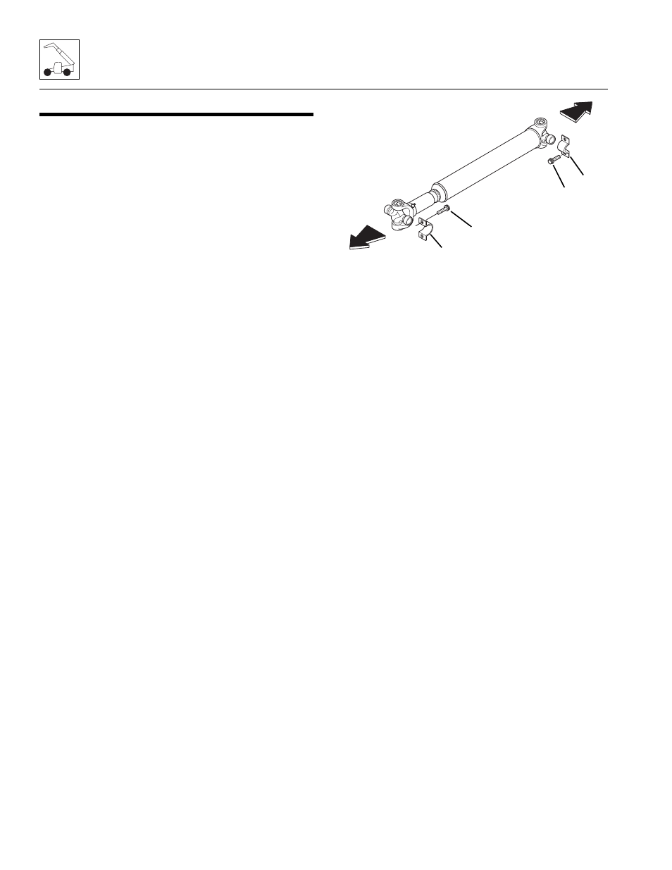
7. Remove the four bolts (1) and two straps (2)
securing the bearing cross to the transmission
output shaft flange.Discard the bolts.
8. Remove the four bolts (3) and two straps (4)
securing the bearing crosses to the axle.
9. Remove the drive shaft assembly.
10. Repeat the above procedure on the rear drive shaft.
5.10.4
Drive Shaft Cleaning and Drying
1. Disassemble and clean all parts using an approved
cleaning fluid. Allow to dry.
2. Remove any burrs or rough spots from all machined
surfaces. Re-clean and dry as required.
5.10.5
Drive Shaft Installation
1. Raise the drive shaft assembly into position. The slip
yoke end of the drive shaft mounts toward the axle. If
reinstalling a drive shaft previously removed, align
the flange yokes according to the alignment marks
made during removal.
Note: Yokes at both ends of the drive shaft must be in
the same plane to help prevent excessive vibration.
2. Apply Loctite
®
243
TM
to all mounting bolts.
3. Install the two straps (2) and four new bolts (1)
securing the bearing crosses to the transmission.
Torque capscrews to 38 Nm (lb-ft).
4. Install the two straps (4) and four new bolts (3)
securing the bearing crosses to the axle. Torque
capscrews to 38 Nm (lb-ft).
5. Repeat the above procedure on the rear drive shaft.
6. Properly connect the battery.
7. Close and secure the engine cover.
8. Unblock the wheels.
9. Remove the Do Not Operate Tag from the ignition
key switch and the steering wheel.
MT0350
TO AXLE
TO TRANSMISSION
1
4
2
3