Jumper settings, Jumper settings -11 – Black Box COMPACT T1 MT850A User Manual
Page 427
Compact T1 - Release 6.1
10-11
OCU-DP Card
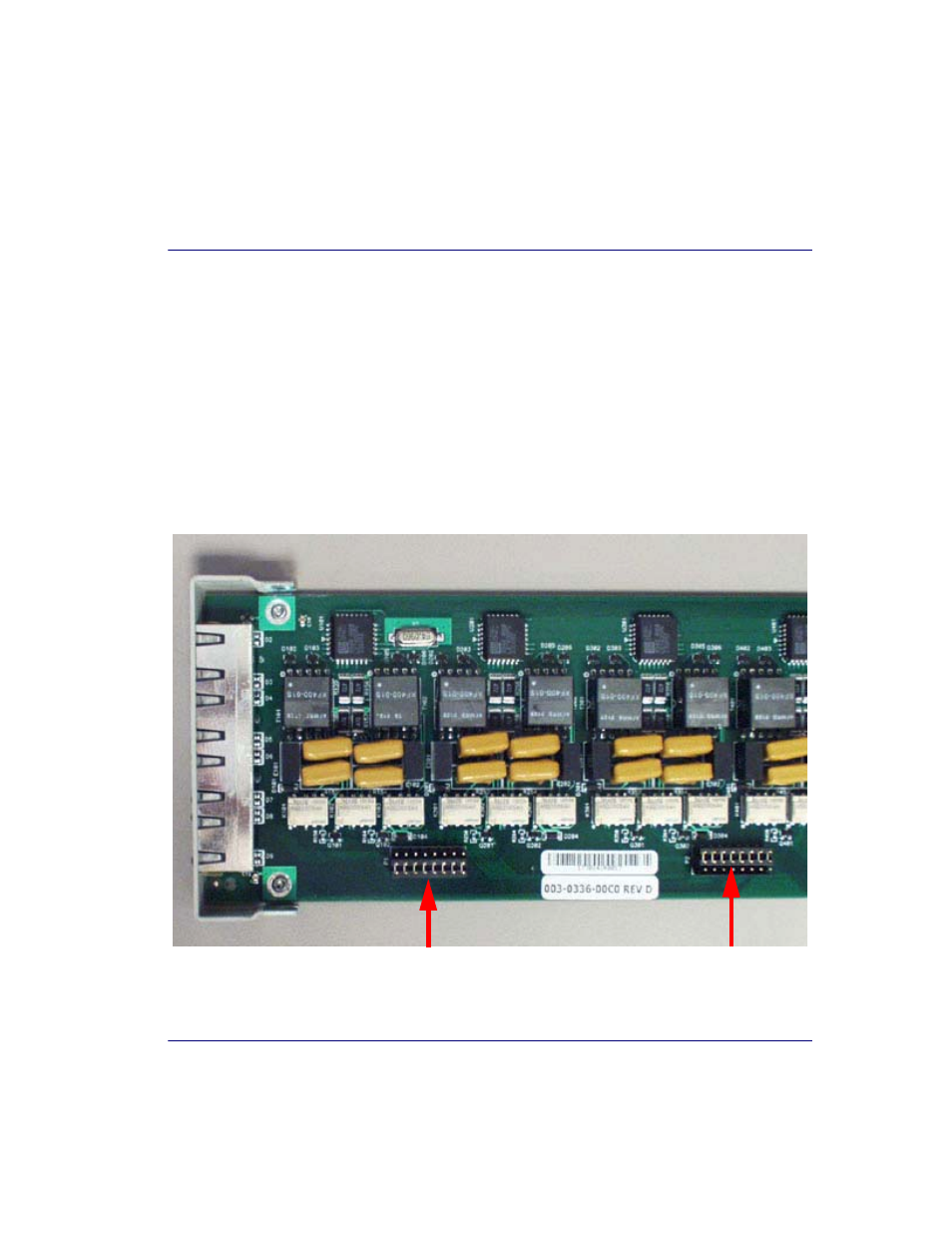
Jumper Settings
Jumper Settings
The P1 and P2 Jumpers are defaulted to RJ-48S, which are the set of pins nearest the
bottom of the service card. With the jumper in this position the signals are routed to the
RJ-48S connector(s) on the face of the card. To route the signals to the 25-pin Telco
connector at the rear of the unit, move the jumpers to the backplane position, which is
the set of pins toward the top of the service card.
P1 applies to connectors 1 and 2 (connector 2 only with the 4 port card).
P2 applies to connectors 3 and 4 (for the four port card only).
P1 is set to
P2 is set to
25-Pin Telco
RJ-48S Position
Position
Top of Card
Front of
Card
See also other documents in the category Black Box Hardware:
- 7000 T1/E1 (4 pages)
- 24 port (263 pages)
- DSU MS (3 pages)
- AC456A-RX-R2 (22 pages)
- EVNSL17A-0500 (1 page)
- CAT5 Shielded Twisted Pair (STP) Patch Cable (3 pages)
- PC to Printer Cables (3 pages)
- PS034E (30 pages)
- SME-4M (3 pages)
- TS020A (1 page)
- RM900A (1 page)
- EXN37215 (1 page)
- MT-RJ Multimode Fiber Optic Cable (2 pages)
- EntraGuard Gold Telephone Entry/Intercom System (3 pages)
- LRS002A-R2 (275 pages)
- CSU/DSU (2 pages)
- 16-Port Type 3 MAU (2 pages)
- FX150A (51 pages)
- SCSI Differential Converter (3 pages)
- 202 (3 pages)
- DATA SHARER RS-232 (3 pages)
- 2000 (3 pages)
- MWU2000-V35 (132 pages)
- KV407A (2 pages)
- Bulk Fiber Optic Cable (2 pages)
- AC1132A (12 pages)
- RS422/485 (30 pages)
- Universal Server Cabinet (2 pages)
- LRB500A (33 pages)
- IC477A-M-R2 (25 pages)
- SHORT-HAUL (6 pages)
- 21834 (2 pages)
- CAT6 (3 pages)
- LRU4240 (218 pages)
- LH1503ALH1504A (3 pages)
- EFN062 (3 pages)
- Ultra2 LVD SCSI Cables and Terminators (2 pages)
- LR1530A-R3 (102 pages)
- GEH-6510 (92 pages)
- VoIP Tool Kit (2 pages)
- CAT5 (3 pages)
- CAT3 (4 pages)
- NEMA 12 (2 pages)
- MD1980A (3 pages)
- CAT5 (2 pages)