Drill a 3/8” hole in each corner – Balboa Water Group Titan Bath Control User Manual
Page 20
Manufactured under one or more of these patents. U.S. Patents: 5332944, 5361215, 5550753, 5559720, 5,883,459, 6253227, 6282370, 6590188, 6976052, 6965815, 7030343, 7,417,
834 b2, Canadian Patent: 2342614, Australian patent: 2373248 other patents both foreign and domestic applied for and pending. All material copyright of Balboa Water Group.
20
7/14/14
Installation Instructions for the Titan 6 Button Panel
material and tools needed:
a) masking tape
b) Power drill with 3/8” drill bit
c) Jig saw
Installation note:
Be sure that the panel will not be
submerged in the water once the tub is filled.
1. Find an appropriate location to install the topside panel.
The surface should be clean and flat so that the adhesive
on the back of the panel will adhere well. Make sure the
cable length will reach the controller(s). Also, make sure
the panel is positioned for easy viewing by the spa user.
2. Take into consideration all of the equipment that will be
installed onto the bath system. Anticipate how long each
cord is to the equipment installed, that is, from the panel,
to the control box, to the pump, or blower, etc.
3. Once an area has been found for the bath panel, apply a
layer or two of masking tape over the area that will be cut
out. The tape will protect the bath surface from getting
marred by the jig saw.
4. After applying the tape, measure a rectangle as shown
in the illustration. When finished, the hole cut-out will be
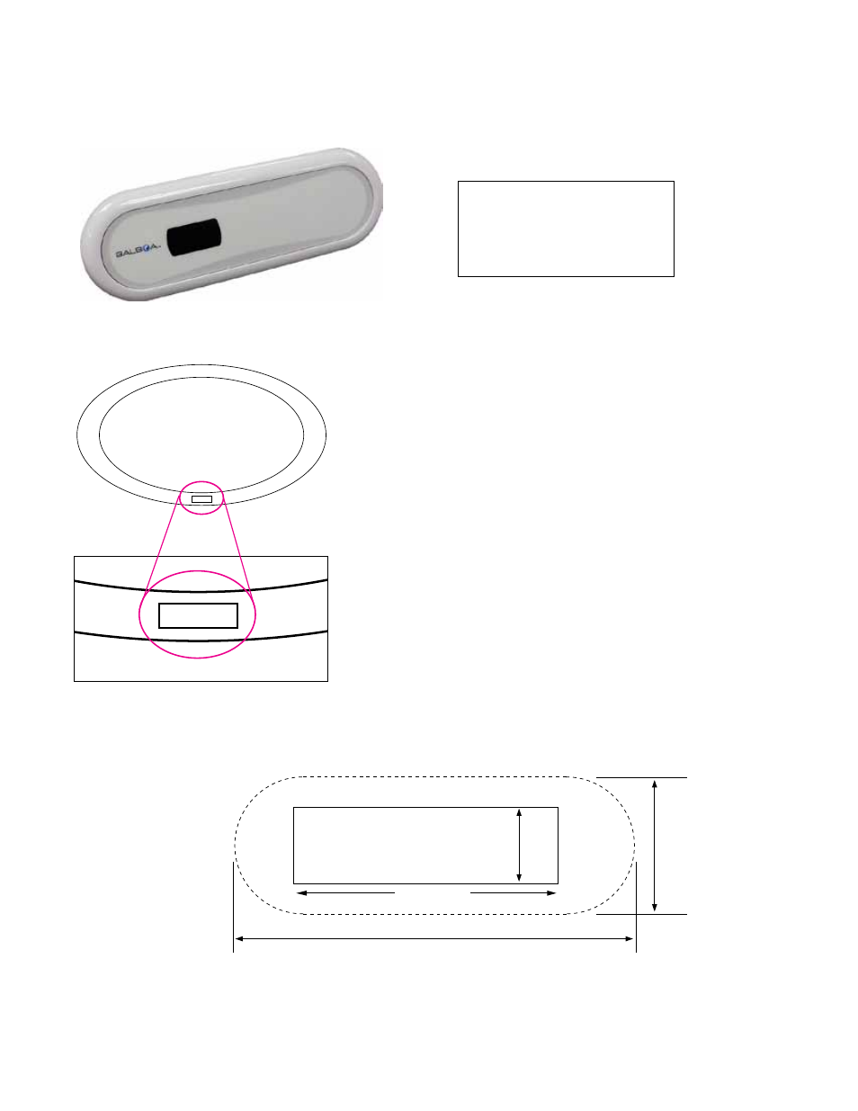
1-3/8” x 4-1/4”.
top view, bath
titan 6 button bath panel cut-out template
a full size diagram for printing is located at the
back of this manual
Titan 6 Button Bath Panel Cut Out Pattern _062512
6.375”
2.375”
1 - 3/8”
4 - 1/4”
Drill a 3/8” hole in each corner