Component installation – Balboa Water Group Titan Bath Control User Manual
Page 19
Manufactured under one or more of these patents. U.S. Patents: 5332944, 5361215, 5550753, 5559720, 5,883,459, 6253227, 6282370, 6590188, 6976052, 6965815, 7030343, 7,417,
834 b2, Canadian Patent: 2342614, Australian patent: 2373248 other patents both foreign and domestic applied for and pending. All material copyright of Balboa Water Group.
19
42135F
Component Installation
InstallatIon overvIeW
Before you begin putting together your bath system, it’s a good
idea to have in mind a layout of where the bath components
are to be installed. A skeletal illustration of installed bath
components is found in the preceding pages.
An important consideration is the location of the topside bath
button control in relation to other equipment. Do not mount
equipment directly under the control panel mounting location in
order to avoid any potential for water to drip directly onto the
equipment. Create a drip-loop in the control panel wires to help
prevent any water traveling down those wires that may drip
onto the equipment.
All three panels use 8-pin DIN connectors. The 8-pin DIN
connector cables plug into any control box. If two control boxes
are used, the panel cable can be plugged into either control box.
If three control boxes are used, the panel cable must be plugged
into the middle control box.
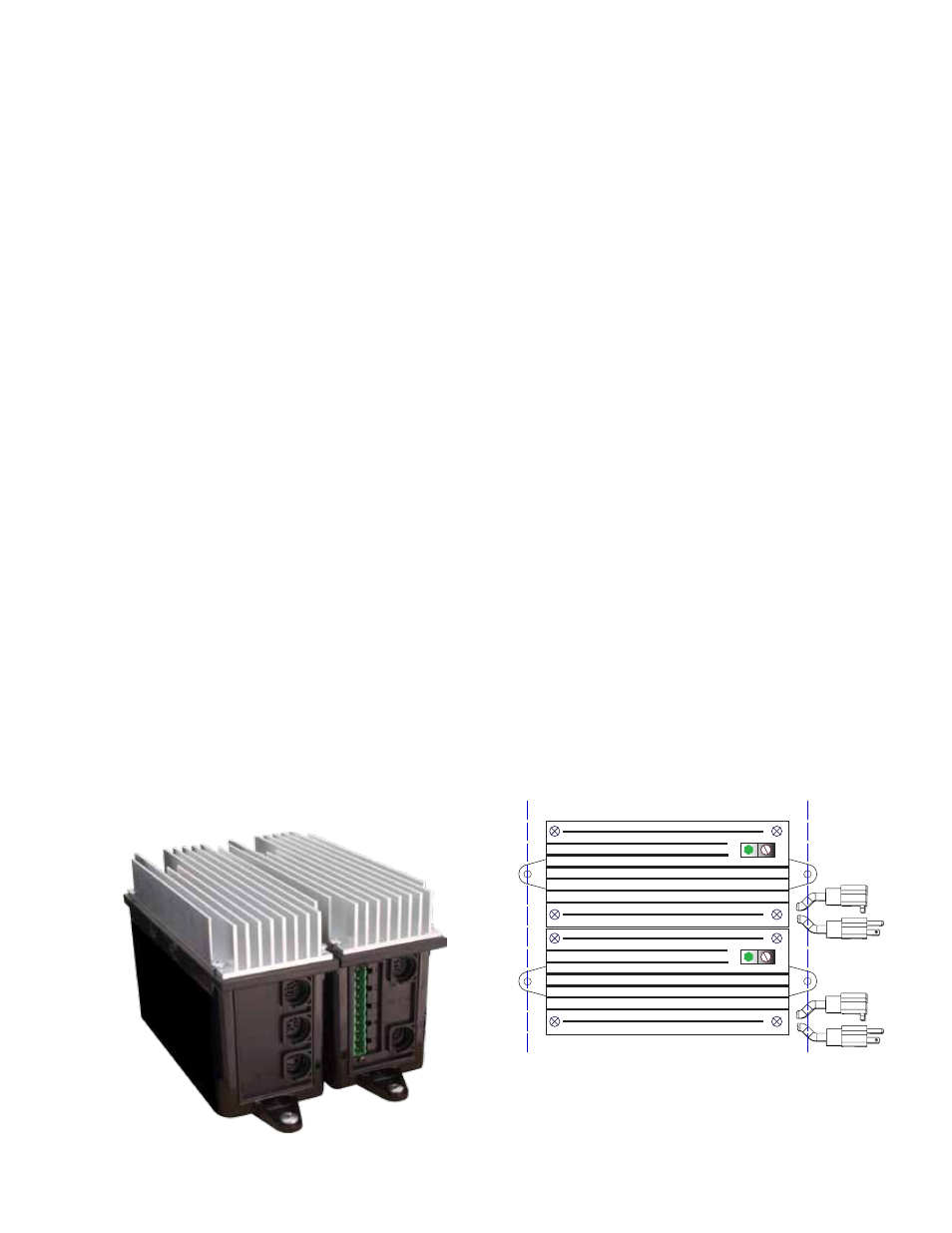
The control boxes can be paired together and will communicate
with each other via IR signals without external connecting
wires or external dipswitch settings. You can have two of
the same type of control boxes (two variable speed boxes
controlling the bath). It is important, however, to place the
control boxes side by side as close as possible to have the
control boxes communicate properly
InstallInG control BoXes, PumPs, and
BloWer
When mounting pumps, blowers, and control boxes, they must
be mounted securely because of vibration and start & stop
cycles.
control BoXes
The panel can be plugged into any of the control boxes. If three
boxes are used, the panel must be plugged into the central
control box. All functions will work providing the following
criteria is observed:
1. The control boxes must be placed side by side.
2. The control boxes must be aligned next to each other.)
3. The panel is configured for the equipment used.
4. Be sure that the sides facing each other are not obstructed,
i.e., papers, stickers, etc. If obstructed, the IR link will not
communicate.
5. Two of the same control boxes can be used together. In
other words, it’s all right to have two 90017 control boxes
controlling your bath, excluding other types of control
boxes. Or, two 90018 boxes can be used together excluding
90017 boxes. And so on.
6. The connectors of the boxes must face in the same
direction (DIN pin connectors facing all one way; power
cords facing all one way).
top view of two control Boxes