Powerblade pbc18 installation guide 97, Mdi-x mdi lnk statu s pwr reset – Allied Telesis AT-PBC18 User Manual
Page 97
PowerBlade PBC18 Installation Guide
97
Caution
Wear a grounding device and observe electrostatic discharge
precautions when installing the PowerBlade module in the chassis.
Failure to observe this caution could result in damage to the
PowerBlade module.
4.
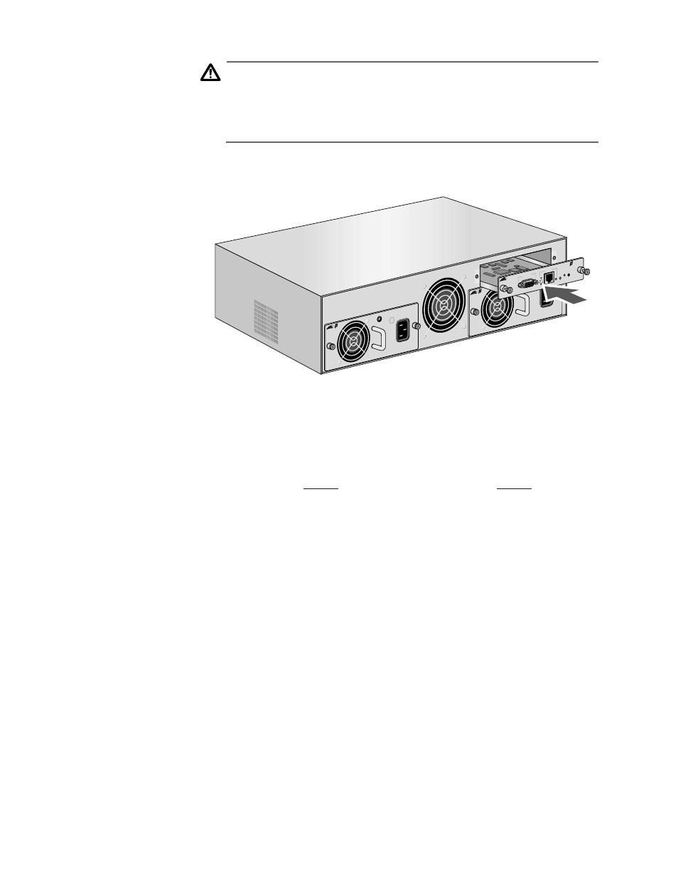
Slide the management module gently into place, seating the
module’s connectors into the chassis’ backplane. See Figure 39.
Figure 39 Installing a Management Module
5.
Secure the management module to the chassis by tightening the
two thumbscrews.
6.
Apply power to the chassis by connecting the AC power cord or DC
wires. Refer to
on page 36 for an AC unit or
for a DC unit.
7.
Check to be sure that the Status and PWR LED on the front of the
management module are green.
8.
For local management, attach one end of an RS-232 cable with a
DB9 connector to the RS-232 port on the management module and
the other end of the cable to a terminal or PC with a terminal
emulator program.
9.
For remote management, connect a Category 3 or better twisted
pair cable with an RJ-45 connector to the 10Base-T port on the
management module and connect the other end of the cable to a
10 Mbps or a 10/100 Mbps port on an Ethernet hub or switch.
10. Set the MDI/MDI-X switch for the 10Base-T port. If the 10Base-T port
is connected to an Ethernet hub or switch, the correct setting for the
switch is probably the MDI (IN) position.
PWR 2
PWR 1
PBPWRA
C
AC IN
PUT
100-2
40AC
50-60
Hz
3A MA
X.
150W
PBM0
2
Manag
ement
MDI-X
MDI
LNK
STATU
S
PWR
RESET
RS-23
2 Term
inal
10Bas
e-T
PBPWRA
C
AC IN
PUT
100-2
40AC
50-60
Hz
3A MA
X.
150W