Guiderail thumbscrew – Allied Telesis AT-PBC18 User Manual
Page 91
PowerBlade PBC18 Installation Guide
91
5.
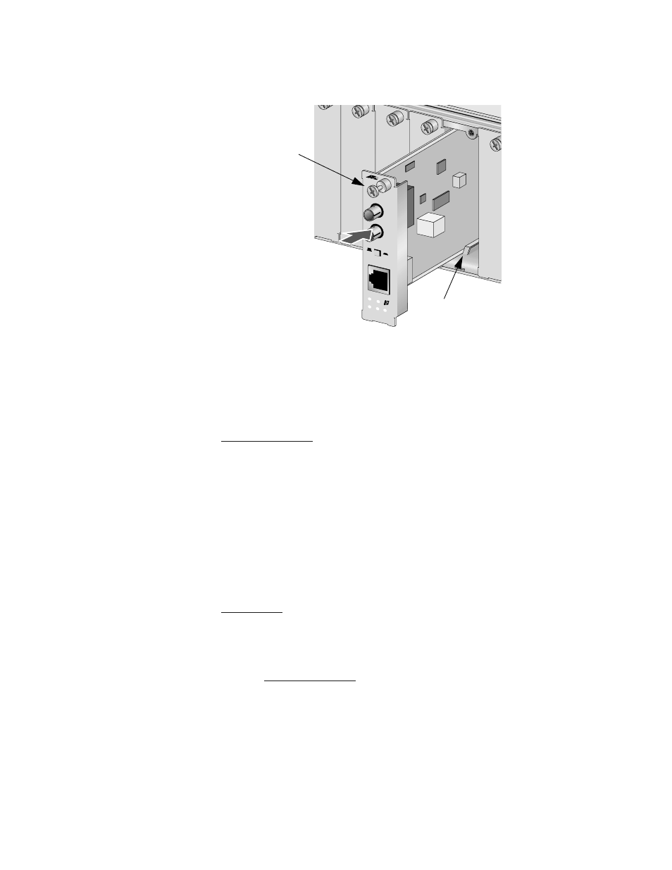
Slide the module into the expansion slot, aligning it with the
guiderails, until it firmly connects to the chassis’ backplane.
Figure 36 Installing a AT-PB200 Series Module
6.
Secure the module to the chassis by tightening the thumbscrew.
7.
Verify that the PR LED is green. If the LED is OFF, refer to
8.
Remove the dust cover from the fiber optic port and attach the fiber
optic cable to the 100Base-FX port. Make sure that the cable
connected to the fiber optic receiver port on the switch is
connected to the transmitter port on the remote end-node and that
the fiber optic transmitter port on the switch is connected to the
receiver port on the end-node.
9.
Attach the twisted pair cable to the 10/100Base-TX port.
10. Set the MDI/MDI-X switch to the appropriate setting. Refer to
on page 81 for information on this feature.
11. Power ON the end-nodes.
12. Check that the LK LED on both ports are green. If the LEDs are OFF,
refer to
The PowerBlade module is now ready for use. Repeat this procedure to
install additional PowerBlade Switches.
PB201
10/100Mbps
F
L
T
X
T
X
R
X
M
M
LK
RX
MDI
MDI-X
LK/A
T
FD
100M
AUTO
PR
Guiderail
Thumbscrew