Head2 - status leds, Head2 - reset button, Head2 - cable specifications – Allied Telesis AT-PBC18 User Manual
Page 95: Status leds, Reset button, Cable specifications
PowerBlade PBC18 Installation Guide
95
Status LEDs
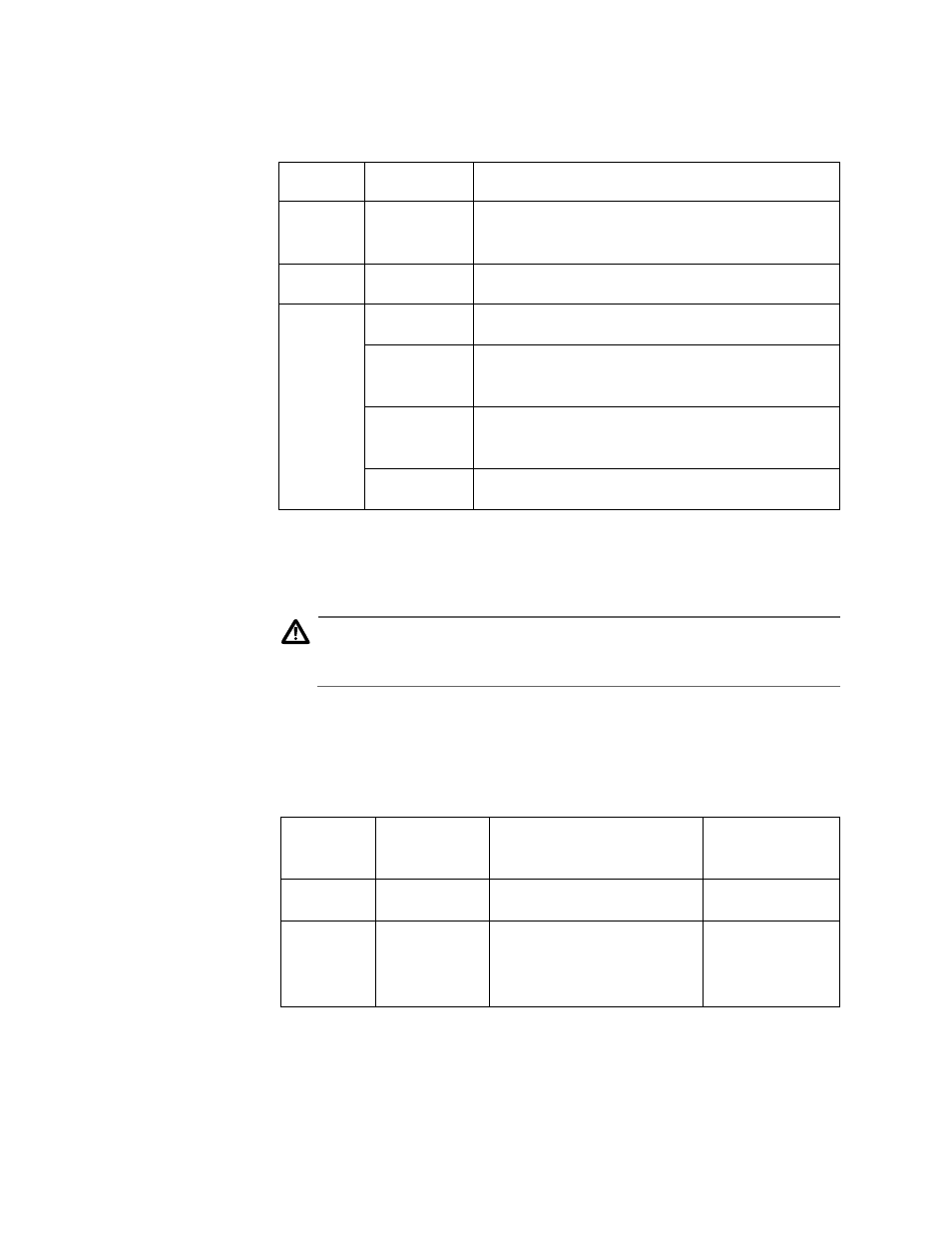
Table 38 lists the status LEDs.
Table 38 AT-PBM02 Status LEDs
Reset Button
The Reset button allows you to reset the management module. You may
need to reset the module after completing the installation, adding or
swapping a power supply, or after upgrading the modules’ firmware.
Caution
Using the Reset button will not interrupt network operations,
except for the 100 Mbps PowerBlade Series Modules.
Cable
Specifications
Table 39 list the connector types and maximum distances for the
AT-PBM02.
Table 39 AT-PBM02 Cabling Specifications
LED
Color
Description
PWR
Green
Power is applied to the management
module.
LNK
Green
A link has been established on the RJ-45 port.
Status
Amber
A self-test is being performed.
Flashing
Amber
The module is downloading the firmware
from a host PC.
Red
The module or management software has
malfunctioned.
Green
The module is installed and online.
Port
Connector
Cable
Maximum
Distance
RS-232
DB9
RS-232 Straight-through
Not applicable
10Base-T
RJ-45
Shielded or unshielded
twisted pair Category 3
or better
100 m (328 ft)