Head1 - installing an optional power supply, Installing an optional power supply, Installing a power supply module 40 – Allied Telesis AT-PBC18 User Manual
Page 40: Mdi-x mdi lnk statu s pwr rese t
Installing a Power Supply Module
40
Installing an Optional Power Supply
To install an optional power supply, perform the following procedure:
Note
It is recommended that you connect the main and optional power
supplies to power outlets on separate power circuits to protect
your chassis from a loss of power due to a power circuit failure.
1.
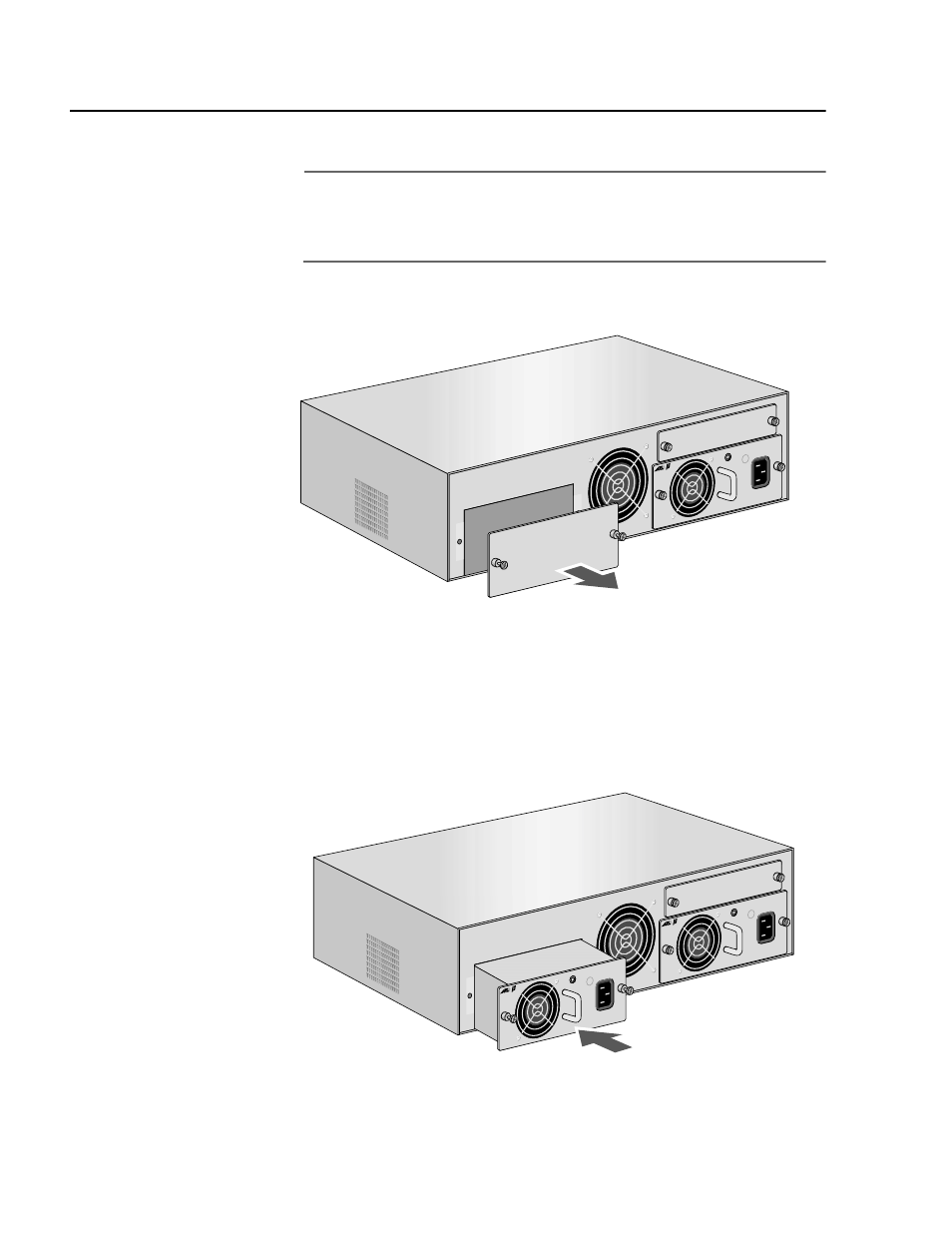
Remove the PWR 2 blank faceplate from the back of the chassis by
loosening the two thumbscrews, as shown in Figure 17.
Figure 17 Removing the Optional Power Supply Blank Faceplate
2.
Remove the power supply from the shipping package and store the
packaging material in a safe location.
3.
Slide the optional power supply into the expansion slot, gently
seating the power supply’s connector into the chassis’ backplane.
See Figure 18.
Figure 18 Installing an Optional Power Supply
PWR 2
PWR 1
PBM02
Manag
ement
MDI-X
MDI
LNK
STATU
S
PWR
RESE
T
RS-23
2 Term
inal
10Bas
e-T
PBPWRA
C
AC IN
PUT
100-2
40AC
50-60
Hz
3A MA
X.
150W
PWR 2
PWR 1
PBM02
Management
MDI-X
MDI
LNK
STATU
S
PWR
RESE
T
RS-23
2 Term
inal
10Bas
e-T
PBPW
RAC
AC IN
PUT
100-2
40AC
50-60
Hz
3A MA
X.
150W
PBPW
RAC
AC IN
PUT
100-2
40AC
50-60
Hz
3A MA
X.
150W