Allied Telesis AT-PBC18 User Manual
Page 37
PowerBlade PBC18 Installation Guide
37
b.
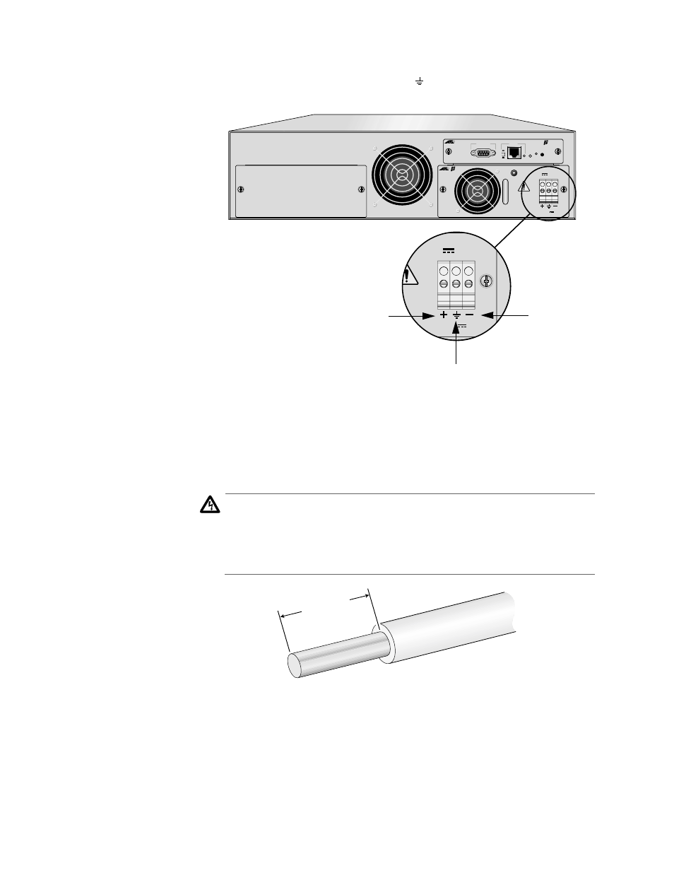
Identify the positive, frame ground and negative terminals
using the positive (+), ground ( ), and negative (-) symbols on
the DC power supply. See Figure 14.
Figure 14 Positive, Ground, and Negative Symbols
c.
Strip the three wires in the cable tray coming from the DC input
power source to 8 millimeters
±
1 millimeters (0.31 inches
±
0.039 inches) using a 14-gauge wire-stripping tool. See Figure
15.
Warning
Do not strip more than the recommended amount of wire.
Stripping more than the recommended amount can create a safety
hazard by leaving exposed wire on the terminal block after
installation.
! 17
Figure 15 Stripped Wire
d.
Connect the frame ground wire to the terminal marked with the
ground symbol by inserting the wire into the terminal block and
tightening the connection with a flathead screwdriver. See
Figure 16.
PWR 2
PWR 1
PBM02
Management
MDI-X
MDI
LNK
STATUS
PWR
RESET
RS-232 Terminal
10Base-T
PBPWRDC
FOR CENTRALIZED DC
POWER CONNECTION,
INSTALL ONLY IN A
RESTRICTED AREA
36-60VDC , 1.0A
DC INPUT
TRALIZED DC
CONNECTION,
L ONLY IN A
CTED AREA
36-60VDC , 1.0A
DC INPUT
Positive
Ground
Negative
8 mm ± 1 mm
(0.31 in ± 0.039 in)