Allied Telesis AT-PBC18 User Manual
Page 74
Installing a Media Converter Module
74
Note
If an AT-PBM02 management module is not installed in the chassis,
the ML LED on the AT-PB15 module will not function properly.
4.
For an AT-PB100 or AT-PB300 Series module, set the
Auto-negotiation switch on the board to enable or disable
auto-negotiation of the duplex mode. Refer to
on page 63 for the location of the switch.
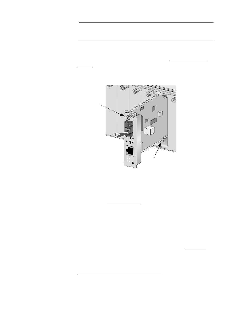
5.
Slide the module gently into place, aligning it with the guiderail,
until it firmly connects to the chassis’ backplane. See Figure 30.
Figure 30 Installing a PowerBlade Module
6.
Secure the module to the chassis by tightening the thumbscrew.
7.
Verify that the PR LED on the front of the module is green. If the LED
is OFF, refer to
8.
Set the ML/LT to the Link Test (LT) position.
9.
Remove the dust cover from the fiber optic port(s).
10. Connect the data cables to the ports on the module.
11. For an AT-PB10, AT-PB100 or AT-PB300 Series module, set the
MDI/MD-X button to the appropriate setting. Refer to
page 45 for information on this feature.
12. For an AT-PB1000 Series module, set the LT BB/LT SA button to
back-to-back or standalone, depending on your topology. Refer to
Link Test Back-to-back/ Standalone Button
information on this feature.
PB14
10Mbp
s
ML
F
L
T
T
X
R
X
M
M
LK
RX
LT
MDI
MDI-X
LK
RX
ML PR
Guiderail
Thumbscrew