Head1 - installing an optional management module, Installing an optional management module, Installing an optional management module 96 – Allied Telesis AT-PBC18 User Manual
Page 96
Installing an Optional Management Module
96
Installing an Optional Management Module
To install an optional management module, perform the following
procedure:
Warning
Installing an optional management module while the chassis is
powered ON could result in damage to the module.
1.
Power OFF the chassis by performing one of the following:
❑
For an AC model, unplug the power cord from the power outlet
and then unplug the power cord for the chassis.
❑
For a DC model, follow the steps below:
Warning
When installing this equipment, always ensure that the frame
ground connection is installed first and disconnected last.
! 18
a.
Remove the positive and negative feed wires from the terminal
block by loosening the screws to the wire connections with a
flathead screwdriver.
b.
Remove the frame ground wire from the terminal block by
loosening the screw to the wire connection with a flathead
screwdriver.
2.
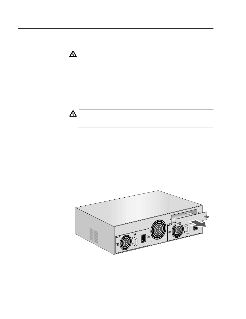
Remove the blank faceplate covering the management module
expansion slot by loosening the two thumbscrews. See Figure 38.
Figure 38 Removing the Management Module Blank Faceplate
3.
Remove the management module from the shipping package and
store the packaging material in a safe place.
PWR 2
PWR 1
PBPWRA
C
AC IN
PUT
100-2
40AC
50-60
Hz
3A MA
X.
150W
PBPWRA
C
AC IN
PUT
100-2
40AC
50-60
Hz
3A MA
X.
150W