Head2 - status leds, Head2 - mdi/mdi-x, Status leds – Allied Telesis AT-PBC18 User Manual
Page 81: Mdi/mdi-x
PowerBlade PBC18 Installation Guide
81
Status LEDs
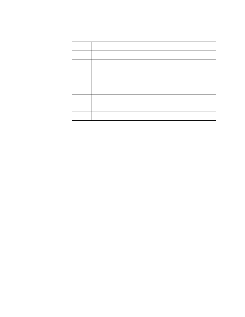
Table 28 list the status LEDs.
Table 28 AT-PB200 and AT-PB202/x Series Status LEDs
MDI/MDI-X
An RJ-45 port on a 10 Mbps or 100 Mbps Ethernet network device can
have one of two possible wiring configurations: MDI and MDI-X. The
RJ-45 port on a PC, router or bridge is typically wired as MDI, while the
twisted pair port on a switch or hub is usually MDI-X.
To connect two 10 Mbps or 100 Mbps network devices together that
have dissimilar port wiring configurations, such as MDI to MDI-X, you use
a straight-through cable. To connect two network devices that have an
RJ-45 port with the same wiring configuration, such as MDI to MDI, you
use a crossover cable.
The PowerBlade 10 Mbps and 100 Mbps switches that have an RJ-45
port feature an MDI/MDI-X button. You can use this button to configure
the twisted pair port on the switch as either MDI or MDI-X, thus
eliminating the need for a crossover cable regardless of the type of
network device you are connecting to the unit.
LED
Color
Description
PR
Green
Power is applied to the switch.
FD
Green
OFF
The switch is operating in full-duplex mode.
The switch is operating in half-duplex mode.
LK/AT
Green
Blinking
A link has been established on the port.
Data is being transmitted or received on the port.
100M
Green
OFF
The port is operating at 100 Mbps.
The port is operating at 10 Mbps.
AUTO
Green
The 10/100Base-TX port is auto-negotiating.